


COMSPHERE 3600 Series Data Service Units
3-6 March 1999 3610-A2-GB41-60
For a DSU equipped with MCMP:
" Procedure
1. From the control DSU, go to the Control (Ctrl)
branch, select LEDs, and then select Aggregate
(Aggr) to monitor the aggregate 56 kbps digital
signal.
2. Go to the Configuration (Confg) branch and select
Poll List (PList) from the menu.
3. Acquire the poll list (Acq). This command starts
the initialization process.
4. Verify that each tributary DSU with MCMP has
been acquired by displaying (Displ) the MCMP
poll list.
If the DSU’s address does not appear on the list,
verify that the missing tributary DSU is equipped
with the MCMP option and configured for MCMP
mode.
After the poll list has been acquired, the LSD and
RXD light-emitting diodes (LEDs) should be
flashing without a pause at the control DSU’s
DCP. Any pause indicates that a tributary on the
poll list is not responding.
5. From the tributary DSU, if a new drop is being
added to an existing MCMP circuit , select Add
from the Poll List menu. This places the tributary
DSU on the control DSU’s poll list.
6. After the tributary DSUs have been added to the
control DSU’s poll list, go back to the Control
(Ctrl) branch, select LEDs, and reassign the
LEDs from the aggregate data path (Aggr) to one
of the DSU ports (Prt1, Prt2, Prt3, etc.).
MCMP capability is now functional, with all tributary
DSUs on the control DSU’s MCMP poll list. At this point,
DSU ports can be assigned to MCMP channels through
the Port Speed (PrtSp) selection from the Configuration
Options (Opts) submenus.
Adding a TDM or MCMP to an
Installed Model 3611 DSU
This section describes the installation procedure for
adding the TDM or MCMP option onto the Model 3611
DSU, and then installing it in a COMSPHERE
3000 Series Carrier.
A non-modular TDM (feature number 3600-F3-206) or
non-modular MCMP (feature number 3600-F3-207) may
be added to a modular or non-modular DSU. A modular
TDM (feature number 3600-F3-204) or modular MCMP
(feature number 3600-F3-205) must be used with the
Modular 3611 DSU.
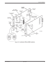
The TDM or MCMP circuit card must be physically
and electrically connected to the DSU, requiring two
adjacent slots in the carrier.
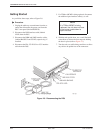
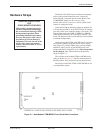
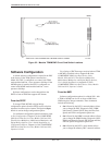
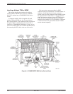
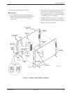
The DSU hardware switches are not changed when the
TDM or MCMP option is installed. The switches on the
non-modular TDM or MCMP circuit card are shown in
Figure 3-1; the switches on the modular TDM or MCMP
circuit card are shown in Figure 3-2. These switches
should not be changed (they are for factory test purposes
only).
Refer to the appropriate section to install either the
non-modular or modular TDM or MCMP.
Before installing the unit:
" Procedure
1. Copy the applicable Configuration Worksheet
from Appendix B.
2. Access Stat (Status branch) and ID (Identity
subbranch).
3. Record the unit’s serial number at the top of
Page 1 of the Configuration Worksheet.
4. Access Confg (Configuration branch).
5. Record the configuration option settings for each
option set (DSU, Diag, etc.).
If a DBM is installed, continue with:
1. Record all Backup Directory entries.
2. Record the unit’s local telephone number (Phone).
For instructions and handling precautions for opening
the DSU, refer to the Hardware Straps and Changing the
Hardware Settings sections of this chapter.