


COMSPHERE 3600 Series Data Service Units
D-22 March 1999 3610-A2-GB41-60
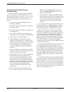
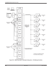
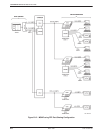
As a result of a network failure in the backbone DDS
network, the control DSU reports a facility alarm to the
NMS. The operator at the NMS workstation is alerted by
the alarm, and examines the circuit’s network map or
circuit profile to see if backup is possible. Supplementary
information about the network addresses of the DBM-Vs
(that are dedicated to the bridge) and their remote DBM
telephone numbers should also be in the circuit profile.
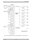
The operator then issues an sf command and enters
originate in the Standby Facility State field to the control
DSU; then a dial command followed by an sf command
and originate in the Standby Facility State field to each of
the DBM-Vs. (A routine command can be created to issue
the command sequence automatically.) The control DSU
reports by activating the digital bridge and switching to
internal timing (Brdg Timing: Int) at the 14.4 kbps
fallback rate. Each DBM-V responds by dialing a
tributary DBM. When connected, the pair of DBMs (the
DBM-V and its tributary DBM) perform a handshake and
exchange passwords, and enter Data mode (ready to send
data).
After the tributary DSU-DBM has answered the call,
each DSU switches the DTE’s data to its DBM. After all
calls are completed, full restoration is accomplished at
14.4 kbps.
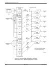
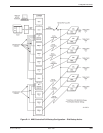
The DBM-Vs provide valid call setup messages to the
NMS. If the NMS does not receive a valid call setup
message from a DBM-V, the NMS operator issues another
dial command followed by the sf command and originate
in the Standby Facility State field to the DBM-V. This
completes the backup circuit and the host computer can
restart the network polling. When backup is completed,
the FEP line may be restarted, if necessary.
During backup, the DSU still reports the facility alarm
to the NMS. When the failure is corrected and the DDS
network is restored, the alarm is turned Off at the
workstation’s Alarm Monitor window. You can request an
aggregate Digital Test to one of the tributary DSUs to
ensure that the DDS network is working correctly.
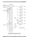
To end the backup session via the NMS, issue
disconnect commands to the control DSU and all its
DBM-Vs. (The NMS restores all control and tributary
DSUs to the DDS network and drops all dial backup calls
by issuing an sf command and release in the Standby
Facility State field to the control DSU, and an sf
command and release in the Standby Facility State field
command, followed by a dial and a q command in the
Number to Dial field to each DBM associated with the
digital bridge. To end the backup session via the SDCP,
address the control DSU and each DBM by issuing the
DrBu (drop backup) command.
Ending the backup session causes the control DSU to
deactivate the bridge, and DSU timing (56 kbps) becomes
the DDS clock source once again. Each DBM-V signals
its tributary that it is dropping the call and hangs up. Each
tributary then switches back to the DDS network, and the
DDS network is again functional. (Between the time that
the bridge is deactivated and the DDS network is
reestablished, errors occur on those tributaries still in
backup.)
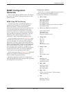
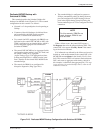
Pertinent configuration options for the central-site
bridge, the extended bridge, a DBM-V, and a tributary
DSU-DBM supporting this application follow. Please note
that all DBM-Vs here should be configured the same –
only the passwords and telephone numbers should differ.
The same holds true for the tributary DSU-DBMs.