


Principles of Operation
4-533610-A2-GB41-60 March 1999
SNA Diagnostic Interface
The SNA Diagnostic Interface option, which is
compatible with IBM’s LPDA-2 (Line Problem
Determination Aid, Revision 2) protocol, enables
management of 3600 Series DSUs from the DCP, a
Paradyne NMS, IBM’s NetView management system, or
all three. All DSUs on the circuit must be 3600 Series
DSUs.
This option is compatible with all other options
available to the 3600 Series DSUs: DBM, TDM, and
MCMP. However, the SNA Diagnostic Interface option is
supported via Port 1 on a TDM or MCMP circuit card.
The 3600 Series DSUs operating with the SNA
Diagnostic Interface option emulate IBM 5822 DSUs;
although they are all data compatible, they are not
diagnostically compatible with IBM 5822 DSUs. A
mixture of 3600 Series and IBM 5822 DSUs will not
support LPDA-2 diagnostics. The SNA Diagnostic
Interface option must be installed in each control and
tributary DSU.
The 3600 Series DSUs operating with the SNA
Diagnostic Interface option can respond to commands
from NetView or an NMS, or the DSU’s DCP. The
3600 Series DSUs respond to commands from an NMS or
NetView on a first-come, first-served basis. The NetView
operator can monitor (read) DSU parameters and line
status and can initiate tests from NetView, but cannot
change DSU configuration options (a NetView
constraint). An NMS operator has complete control of the
network, and can change network configuration options as
well as access sophisticated alarm-tracking reports.
The carrier-mounted Model 3611 DSU or the
standalone Model 3610 DSU can receive the SNA
Diagnostic Interface firmware. Either model may be
configured as the control of a circuit that is to be managed
by the NetView management system.
Refer to Chapter 6 of the COMSPHERE 3600 Series
Data Service Units, Models 3610 and 3611, Operator’s
Guide for configuration option information. Refer to the
COMSPHERE 3600 Series Data Service Units,
Models 3610 and 3611, Dial Backup Module and SNA
Diagnostic Interface Options, Applications Guide for
additional SNA Diagnostic Interface information.
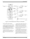
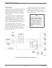
LPDA-2 Addressing
The addressing scheme for LPDA-2 establishes a
relationship between the link segments (primary circuit,
extended circuit) and the remote DSUs populating the
circuit. It allows you to target a link segment or a
particular control-tributary DSU pair in the circuit for
diagnostic testing. The LPDA-2 address is independent of
the DSU network address associated with an NMS or
DCP command, although you may choose to assign the
same value to each.
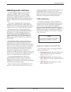
NOTE
In all of the illustrations, the LPDA-2
addresses are shown in decimal.
Assigning an Address to the Control DSU
The following rules apply to assigning the LPDA-2
address to control DSUs:
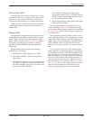
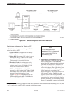
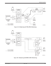
1. Link Segment Level 1. The control DSU closest
to the NetView host is typically assigned the
address 1 (Figure 4-41).
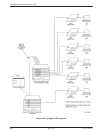
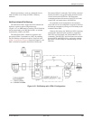
2. Link Segment Level 2. An extended control
DSU, if present, is typically assigned the address 2
(Figure 4-42).
3. Valid Addresses. Valid addresses for control
DSUs range from 1 to 255.