


Pin Assignments
C-153610-A2-GB41-60 March 1999
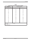
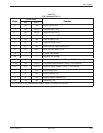
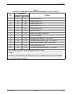
Table C-7
EIA-232/V.24 TDM/MCMP Connector (Modular and Standalone – Ports 2 through 6)
Pin
Circuit Name
F nction
Pin
EIA-232
1
CCITT/V.25
Function
2 BA 103 Transmit Data (TXD)
3 BB 104 Received Data (RXD)
4 CA 105 Request-to-Send (RTS)
5 CB 106 Clear-to-Send (CTS)
6 CC 107 Data Set Ready (DSR)
7 AB 102 Signal Ground (SG)
8 CF 109 Received Line Signal Detect (LSD)
9 — — Positive Test Voltage
12
2
CI 112 Data Signal Rate Selector I — DCE Source
15 DB 114 Transmitter Signal Element Timing — DCE Source
17 DD 115 Receiver Signal Element Timing — DCE Source
20 CD 108.2 Data Terminal Ready (DTR)
24 DA 113 Transmitter Signal Element Timing — DTE Source
1
EIA-232 refers to EIA-232-D without the loopbacks and ring indicator.
2
During normal operation, Pin 12 is ON for Ports 2 through 6. During dial backup, Pin 12 is Off for Ports 2
through 6.
In TDM mode, if External Lead is configured for Rate (Ext Leads: Rate), then this lead is used for speed
selection on a port connecting to an analog private line (APL) extended circuit when the DDS backbone
goes into backup. This pin signals the APL modem to fall back to the predetermined backup speed if the
APL modem has fallback capability.