


Model 3611 Installation
3-33610-A2-GB41-60 March 1999
Hardware Straps
HANDLING PRECAUTIONS
FOR
STATIC-SENSITIVE DEVICES
This product is designed to protect
sensitive components from damage
due to electrostatic discharge (ESD)
during normal operation. When
performing installation procedures,
however, take proper static control
precautions to prevent damage to
equipment. If you are not sure of the
proper static control precautions,
contact your nearest sales or service
representative.
The Model 3611 DSU has one switch and one jumper
on the circuit card that should be reset, if necessary,
before the DSU is inserted into the carrier. Refer to the
COMSPHERE 3600 Series Data Service Units,
Models 3610 and 3611, Operator’s Guide, which can be
ordered, to change the straps.
When the Test Mode Indication jumper is enabled, the
V.35 lead NN and Pin 25 on the EIA-232-D/V.24 interface
go to ON (+EIA level) condition during a Test mode. This
is the default setting on a DBM-V, DBM-S, or DBM-D.
When disabled, the leads do not change to indicate a Test
mode. The indicator lead for each interface can be enabled
or disabled independently.
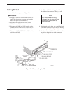
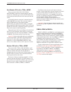
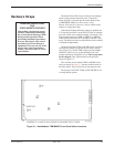
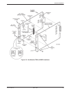
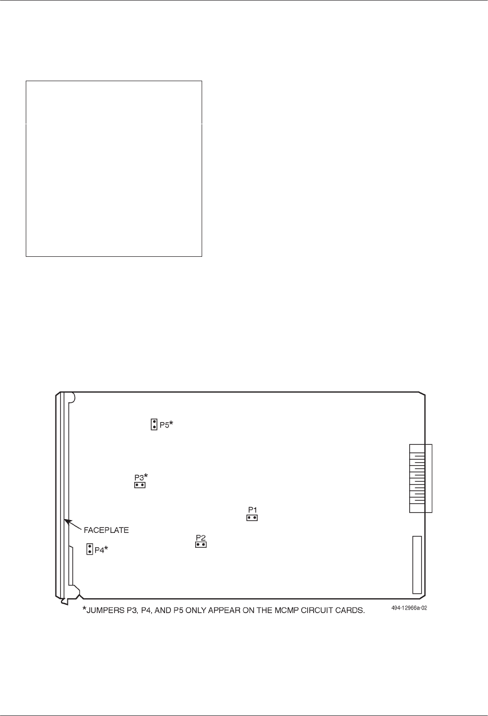
On the non-modular TDM or MCMP circuit card, there
are hardware (jumper) straps that are for factory testing
only (Figure 3-1). On the TDM circuit card, the jumpers
labeled P1 and P2 are set; on the MCMP circuit card,
jumpers labeled P1 through P5 are set. These straps must
not be changed. They should remain in the positions
shown in Figure 3-1.
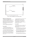
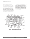
The switches on the modular TDM or MCMP circuit
cards are shown in Figure 3-2, but they should remain in
the ON position. They are for factory test purposes only.
Most straps for the DSU-TDM or DSU-MCMP are set
as configuration options.
Figure 3-1. Non-Modular TDM/MCMP Circuit Card Switch Locations