


3-13610-A2-GB41-60 March 1999
Model 3611 Installation
Overview 3-1. . . . . . . . . . . . . . . . . . . . . . . . . . . . . . . . . . . . . . . . . . . . . . . . . . . . . . . . . . . . . . . . . . . . . . . . . .
Non-Modular DSU with a TDM or MCMP 3-2. . . . . . . . . . . . . . . . . . . . . . . . . . . . . . . . . . . . . . . . . . . .
Modular DSU with a TDM or MCMP 3-2. . . . . . . . . . . . . . . . . . . . . . . . . . . . . . . . . . . . . . . . . . . . . . . . .
DBM-Vs/DBM-Ss/DBM-Ds 3-2. . . . . . . . . . . . . . . . . . . . . . . . . . . . . . . . . . . . . . . . . . . . . . . . . . . . . . . .
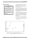
Hardware Straps 3-3. . . . . . . . . . . . . . . . . . . . . . . . . . . . . . . . . . . . . . . . . . . . . . . . . . . . . . . . . . . . . . . . . . . .
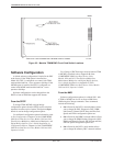
Software Configuration 3-4. . . . . . . . . . . . . . . . . . . . . . . . . . . . . . . . . . . . . . . . . . . . . . . . . . . . . . . . . . . . . . .
From the SDCP 3-4. . . . . . . . . . . . . . . . . . . . . . . . . . . . . . . . . . . . . . . . . . . . . . . . . . . . . . . . . . . . . . . . . .
From the NMS 3-4. . . . . . . . . . . . . . . . . . . . . . . . . . . . . . . . . . . . . . . . . . . . . . . . . . . . . . . . . . . . . . . . . . .
Verification Testing 3-5. . . . . . . . . . . . . . . . . . . . . . . . . . . . . . . . . . . . . . . . . . . . . . . . . . . . . . . . . . . . . . . . . .
Adding a TDM or MCMP to an Installed Model 3611 DSU 3-6. . . . . . . . . . . . . . . . . . . . . . . . . . . . . . . . . .
Installing a Non-Modular TDM or MCMP 3-7. . . . . . . . . . . . . . . . . . . . . . . . . . . . . . . . . . . . . . . . . . . . .
Power-Up Routine 3-8. . . . . . . . . . . . . . . . . . . . . . . . . . . . . . . . . . . . . . . . . . . . . . . . . . . . . . . . . . . . . . . .
Installing a Modular TDM or MCMP 3-10. . . . . . . . . . . . . . . . . . . . . . . . . . . . . . . . . . . . . . . . . . . . . . . . .
Removing a TDM or MCMP from an Installed Model 3611 DSU 3-13. . . . . . . . . . . . . . . . . . . . . . . . . . . . .
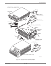
Overview
The Model 3611 DSU-TDM or DSU-MCMP is
designed for installation in a COMSPHERE 3000 Series
Carrier, which supplies operating power and provides
interfaces for connecting to the DDS and, if required,
analog networks. Up to 16 DSUs can be installed in a
COMSPHERE 3000 Series Carrier.
A Model 3611 DSU (modular or non-modular) is
delivered with default strap settings and factory-installed
software options. The DSU is ready to connect to the
network and is configured as a control DSU for operation
at 9.6 kbps on a point-to-point circuit, with diagnostic
protocol set to ADp. When a TDM or MCMP is installed,
Port 1 of the DSU is configured to operate at 9.6 kbps
with the TDM or MCMP capability enabled; all other
ports are disabled.
NOTE
In this guide, Model 3611 refers
to either the modular or the
non-modular DSU-TDM or
DSU-MCMP, unless otherwise
specified.
A shared diagnostic control panel (SDCP), installed in
the carrier, is required for installation and maintenance of
the Model 3611 DSU-TDM or DSU-MCMP.
Installation of the DSU-TDM or DSU-MCMP and
carrier-related equipment consists of the following
procedures, which should be performed in the order listed.
• Changing hardware straps (if necessary)
• Physical installation of the DSU-TDM or
DSU-MCMP
• Network diagnostic connection
• Software configuration
• DDS network (or LADS) connection
• PSTN or switched 56 kbps network connection
(if a DBM is installed)
• DSU DTE connection
• Operation verification
This chapter tells you how to perform the procedures.
For electrical connection, network diagnostic connection,
PSTN and switched 56 kbps network connection, DDS
network or LADS connection, and DSU DTE connection
information, refer to the COMSPHERE 3000 Series
Carrier, Installation Manual.
3