


DSU Operations
5-33610-A2-GB41-60 March 1999
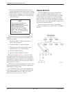
Status Indicators
The status indicators on the Model 3610 DSU’s DCP
and on the Model 3611 DSU’s faceplate continuously
provide information on the current operating condition of
the DSU. All of the status indicators on the Model 3610
appear on its DCP, whereas the status indicators of the
carrier-mounted Model 3611 DSU are spread across the
following interfaces:
• SDCP
• Faceplate of the Model 3611 DSU (Figures 5-1
and 5-2)
• Faceplate of the TDM or MCMP circuit card
(Figures 5-1 and 5-2)
• Faceplate of the DBM-V, DBM-S, or DBM-D, if
installed (Figure 5-3)
• Faceplate of the shared diagnostic unit (SDU), if
installed
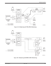
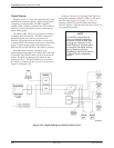
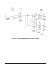
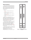
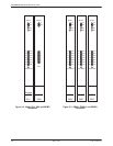
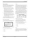
Figures 5-1 and 5-2 show the faceplates of a
Model 3611 DSU with the TDM option and a DSU with
the MCMP option. The DSU faceplate provides network,
DSU, and DTE interface status; the TDM or MCMP
faceplate provides additional device status and port-
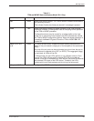
selection information. Table 5-1 describes the function of
the TDM and MCMP faceplate indicators.
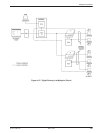
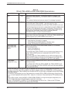
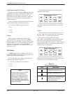
The DBM-V, DBM-S, and DBM-D circuit cards are
used with a digital bridge for multipoint dial backup. The
status indicators on these circuit cards continuously
provide information on the DBM-V’s, DBM-S’s, or
DBM-D’s current operating condition, functioning in a
manner similar to the indicators on the DSU. Table 5-2
describes the function of the DBM-V, DBM-S, or DBM-D
faceplate indicators.
SDCP and SDU status indicators are unchanged by the
presence of a TDM or MCMP circuit card. To view SDCP
and SDU status indicator tables, refer to the
COMSPHERE 3600 Series Data Service Units,
Models 3610 and 3611, User’s Guide or the
COMSPHERE 3000 Series Carrier Installation Manual.
OK
Alrm
Status
TDM
496-12350c-01
3600
1
2
3
4
5
6
Port
TXD
RXD
RTS
CTS
DSR
DTR
LSD
103
104
105
106
107
108
109
OK
Alrm
Test
Dial
Status
Front Panel
Multirate
DSU
3611
496-12349-01
Figure 5-1. Model 3611 DSU and TDM
Faceplates