


COMSPHERE 3600 Series Data Service Units
3-12 March 1999 3610-A2-GB41-60
To install the 6-port connector module and add the
TDM or MCMP option to a Modular 3611 DSU:
" Procedure
1. At the rear of the carrier, set the tabs on the 6-port
connector module into the slotted grooves on the
carrier’s backplane. (Note that the connector
module occupies two slot positions.) Make sure
the connector module uses the same slot positions
intended for the modular DSU-TDM or
DSU-MCMP circuit cards.
2. Loosely fasten the screws attached to the
connector module, allowing for slight adjustment
that may be needed when installing the modular
DSU-TDM or DSU-MCMP circuit cards. The two
screws on the connector module must be
alternately fastened.
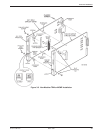
3. On the ESD workpad, insert the two plastic
snaplock posts into their respective holes (See
Figure 3-5).
4. Attach the four metal standoff posts to the DSU
with the four Phillips-head screws and flat
washers. Tighten the screws until the standoff
posts fit snugly against the circuit card. Do not
overtighten.
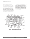
5. On the ESD workpad, orient the DSU to its
upright position, with the faceplate over the edge
of the table (so the latches hang over) and pointing
toward you (just as it would sit in the carrier).
Orient the modular TDM or MCMP circuit card in
the same manner, to the immediate right of the
modular DSU circuit card.
Keeping the modular circuit cards (DSU and TDM
or MCMP) perpendicular to the work surface,
move the circuit cards closer to one another,
ensuring that their bottom edges are flat against
the work surface.
Look between the circuit cards to guide the
double-ended pin header with an integral ferrite
choke into its mating connector on the modular
TDM or MCMP. At the same time, ensure that the
snaplock posts are aligned with their mating holes
in the modular TDM or MCMP. Make sure that
the double-ended pin headers are properly aligned.
Then, snap the snaplock posts into the modular
TDM or MCMP.
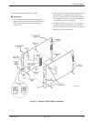
6. Use the remaining four Phillips-head screws and
flat washers to secure the standoff posts to the
modular TDM or MCMP.
7. At the front of the carrier, make sure that both the
top and bottom edges of the modular DSU-TDM
or DSU-MCMP circuit cards are correctly aligned
in their respective circuit card guides. Then, slide
the modular DSU-TDM or DSU-MCMP unit into
the carrier and press the faceplate latches on both
circuit card faceplates to secure the circuit cards
into the connector module.
8. Rotate the circuit pack lock on the modular DSU
circuit card faceplate back into the closed position
and tighten the screw (Figure 3-5).
9. Install the black-banded end of the double-ended
pin header with an integral ferrite choke into its
mating connector on the DSU. Make sure that the
double-ended pin header is fully seated.
10. Return to the rear of the carrier and tighten the
screws on the connector module.
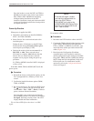
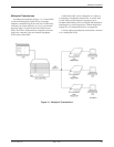
11. Connect the DTE interface cables (Figure 3-4).
Install a ferrite choke (provided with the 6-port
connector module) on each DTE cable, as close to
the cable connector as possible. If your
configuration requires a crossover cable (part
number 4951-035F), see the documentation
provided with the cables.
12. On power-up, the DSU determines what options
are installed. Refer to the Power-Up Routine
section of this chapter.
13. Based upon the Configuration Worksheet
completed prior to the installation, make any
desired configuration option changes in the DSU,
Diag (DSU, DBM, and Gen), DBM, Gen, Bckup,
MUX (Setup and Prt1 through Prt6), PrtSp, and
LPDA option sets. For information on these
option sets, refer to the Configuration Branch
section in Chapter 5.
14. Verify operation; refer to the Verification Testing
section of this chapter.
At this point, MCMP capability is functional, with all
tributary DSUs on the MCMP poll list, and DSU ports can
be assigned to MCMP channels.