


COMSPHERE 3600 Series Data Service Units
4-24 March 1999 3610-A2-GB41-60
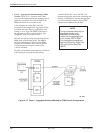
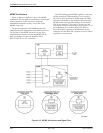
MCMP Architecture
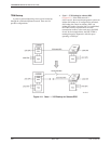
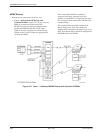
Figure 4-18 shows a high-level view of the MCMP
architecture. The data paths are established as in the TDM
mode of operation via the data router. Additional
multichannel multipoint circuitry is activated on the
MCMP circuit card.
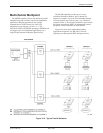
The port arrangement on the MCMP circuit card is
identical to the port arrangement on the TDM circuit card.
The first port of the MCMP circuit card is part of the
communications interface between the MCMP and the
DSU, and emerges as a physical interface (either
EIA-232-D/V.24 or V.35) on the DSU.
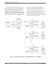
The DTE cabling for the MCMP capability is the same
cabling used for the TDM capability. For non-modular
Model 3611 DSUs operating in MCMP mode, the TDM
interface cable attaches to the multiport connector on the
MCMP circuit card to provide cabling to five individual
EIA 25-pin connectors. This cable is six feet long, and
each fan-out section is one foot long. (See Appendix C for
pin assignments.) For modular Model 3611 DSUs or
Model 3610 DSUs operating in MCMP mode, all port
connectors are individual and a separate crossover cable is
required for each connector.
Figure 4-18. MCMP Architecture and Signal Flow