


COMSPHERE 3600 Series Data Service Units
2-12 March 1999 3610-A2-GB41-60
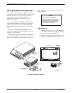
Verification Testing
Perform verification testing after any installation. After
installing and configuring a network, including control
and tributary DSUs, the DDS network and, if appropriate,
DBMs and their dial connections, perform the following
series of tests from the control DSU (using the DCP, an
async terminal, or an NMS) to verify network operation.
" Procedure
1. Request a device Identity (ID from the Status
branch) report from each tributary to ensure that
the DSU is addressed properly.
2. Perform a Digital Test (on the DDS circuit) to
ensure that the network is functioning. Refer to the
Digital Test section of Chapter 5.
For a DSU configured for TDM mode, perform a
Digital Test on each active port.
For a DSU configured for MCMP mode, perform a
Digital Test on each tributary DSU on the
aggregate channel.
For a digital-sharing group, perform a Digital Test
on the lower-numbered port in the digital-sharing
group only.
NOTE
A control DSU can originate a
Digital Test in a point-to-point or
multipoint network. A tributary
DSU can originate a Digital Test
in a point-to-point network only,
provided the configuration
option Respond to Remote
Digital Loopback
(RespondRDL) is enabled in
the control.
For a DSU equipped with a DBM:
" Procedure
1. Select the Dial command from Bckup while in
Idle Mode to establish a dial call to the tributary to
test for dial tone, and verify that the DSU can
initiate and receive calls.
2. Select the →Dial command to switch the data to
the PSTN or switched 56 kbps circuit (enter Dial
Backup mode) to ensure that both DSUs have
been configured correctly.
3. Perform a Digital Test on both the DBM and the
PSTN or switched 56 kbps circuit.
For a DSU equipped with both DBM and TDM or
MCMP, perform a Digital Test on each of the
TDM or MCMP ports in Dial Backup mode on the
PSTN or switched 56 kbps circuit.
4. Drop the backup.
For a DSU equipped with MCMP:
" Procedure
1. From the control DSU, go to the Control (Ctrl)
branch, select LEDs, and then select Aggregate
(Aggr) to monitor the aggregate 56 kbps digital
signal.
2. Go to the Configuration (Confg) branch and select
Poll List (PList) from the menu.
3. Acquire the poll list (Acq). This command starts
the initialization process.
4. Verify that each tributary DSU with MCMP has
been acquired by displaying (Displ) the MCMP
poll list.
If the DSU’s address does not appear on the list,
verify that the missing tributary DSU is equipped
with the MCMP option and configured for MCMP
mode.
After the poll list has been acquired, the LSD and
RXD light-emitting diodes (LEDs) should be
flashing without a pause at the control DSU’s
DCP. Any pause indicates that a tributary on the
poll list is not responding.
5. From the tributary DSU, if a new drop is being
added to an existing MCMP circuit, select Add
from the Poll List menu. This places the tributary
DSU on the control DSU’s poll list.
6. After the tributary DSUs have been added to the
control DSU’s poll list, go back to the Control
(Ctrl) branch, select LEDs, and reassign the
LEDs from the aggregate data path (Aggr) to one
of the DSU ports (Prt1, Prt2, Prt3, etc.).
MCMP capability is now functional, with all tributary
DSUs on the control DSU’s MCMP poll list. At this point,
DSU ports can be assigned to MCMP channels through
the Port Speed (PrtSp) selection from the Configuration
Options (Opts) submenu.