


Model 3611 Installation
3-73610-A2-GB41-60 March 1999
Installing a Non-Modular TDM or MCMP
This section describes the procedure for adding a
non-modular TDM or MCMP circuit card onto a
Model 3611 DSU and then into a COMSPHERE
3000 Series Carrier.
One of two special cables that attach to the multiport
connector on the TDM or MCMP circuit card must be
available when adding a non-modular TDM or MCMP:
the TDM Interface Cable or the Digital Bridge Interface
Cable. (Specify which cable is required at the time of
purchase).
To install a TDM or MCMP onto a Model 3611 DSU:
" Procedure
1. Disconnect the DTE interface cable from the
DSU. (It is not necessary to power down the
carrier.)
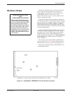
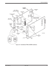
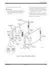
2. Use a Phillips screwdriver to loosen the screw
holding the circuit pack lock on the Model 3611
DSU, and rotate the lock to the open position
(Figure 3-3).
3. Pull out and down on the latch at the bottom of the
DSU’s faceplate until the circuit card starts to
come out of its slot in the carrier. Pull the circuit
card free of the carrier and set the DSU on a clean,
ESD (anti-static) workpad.
4. Insert the two plastic snaplock posts into their
respective holes in the DSU circuit card (see
Figure 3-3).
5. Insert the plastic slotted screw located near the top
and rear of the DSU circuit card through its
associated hole on the DSU and thread a standoff
post onto the screw. Using a flat-blade
screwdriver, tighten the plastic slotted screw until
the standoff fits snugly against the circuit card; do
not overtighten.
CAUTION
A plastic screw must be used
on the far side of the DSU to
avoid contact with the printed
circuit wire path. Use care in
handling the circuit card and
screws to avoid cutting
traces.
6. Attach the two remaining standoff posts to the
DSU with the two Phillips-head screws and flat
washers. Tighten the screws until the standoff
posts fit snugly against the circuit card; do not
overtighten.
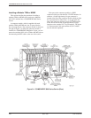
7. Install the black-banded end of the double-ended
pin header into its mating connector on the DSU.
Make sure that the double-ended pin header is
fully seated.
If the double-ended pin header and its mating
connector do not fit, you have an older model
DSU. Contact your service representative.
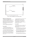
On a flat anti-static work surface, orient the DSU
to its upright position, with the faceplate over the
edge of the table (so the latches hang over) and
pointing toward you (just as it would sit in the
carrier). Orient the TDM or MCMP circuit card in
the same manner, to the immediate right of the
DSU circuit card.
8. Keeping the circuit cards perpendicular to the
work surface, move the circuit cards closer to one
another, ensuring that their bottom edges are flat
against the work surface. Look between the circuit
cards to guide the double-ended pin header into its
mating connector on the TDM or MCMP circuit
card. At the same time, ensure that the snaplock
posts are aligned with their mating holes in the
TDM or MCMP circuit card. Make sure that the
double-ended pin headers are properly aligned.
Then, snap the snaplock posts into the TDM or
MCMP circuit card.
9. Use the remaining three Phillips-head screws and
flat washers to secure the standoff posts to the
TDM or MCMP circuit card.
10. At the front of the carrier, hold the DSU-TDM or
DSU-MCMP circuit cards unit vertically, with the
latches on the faceplates in the open position.
Making sure that both the top and bottom edges of
the DSU and TDM or MCMP circuit cards are
correctly aligned in the respective circuit card
guides, slide the DSU-TDM or DSU-MCMP unit
into the slots until the power and network
connectors seat firmly into the mating connectors
on the backplane.