


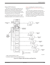

Principles of Operation
4-473610-A2-GB41-60 March 1999
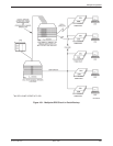
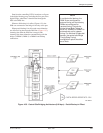
Tributaries with Multiple Call capability should use
this capability to increase their probability of connection
to the bridge. The telephone numbers of all DBMs on the
bridge should be entered into the tributary’s directory.
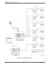
The digital bridge must be configured for the
appropriate number of ports (one port for each drop to be
backed up) and the Bridge Rate configuration option must
be set to =DSU. (The Bridge Rate configuration option is
discussed in the MUX Configuration Options section of
Chapter 5.) The DBMs associated with the digital bridge
should have security options compatible with the tributary
DBMs.
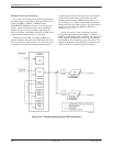
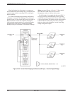
When a tributary DSU senses a DDS network failure
condition, it places a call to one of the DBMs associated
with the digital bridge. The call is answered by the control
DBM-V, DBM-S, or DBM-D, the DBM raises DSR,
which then turns on DTR at the digital bridge port. The
EIA status command can be used to determine which
ports are active by checking the DTR Lead status. Each
tributary sensing a network failure will place a backup
call.
Automatic DDS Restoration
When the DSU rate equals the DBM rate, the tributary
DSUs can be configured to drop the backup call and
switch back to the DDS network when they detect that the
DDS network is restored for a customer-specified time.
This feature automatically restores all control and
tributary DSUs to the DDS network and drops all dial
backup calls. There is no test of the DDS line during
automatic restoration of multipoint tributary DSUs.
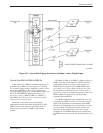
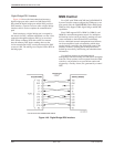
Setup – DBM Rate Less Than DSU Rate*
For a network running at DDS 19.2 kbps or greater
with DBM-Vs (V.32 backup only), only full backup is
possible, and it can only be accomplished manually: either
from the SDCP or initiated by an NMS. In either case,
commands are sent to the control DSU having the digital
bridge capability and to the DBM-Vs, commanding the
control DSU to activate the digital bridge and the
DBM-Vs to call the DBMs at the tributary sites.
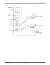
The DBM-Vs and tributaries need to be paired off and,
in each DBM-V, a pointer must be set to the telephone
number of the associated tributary DBM. Thus, each
DBM-V will call a different DBM. Each DBM/DBM-V
pair should have compatible security options.
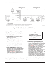
If there is a failure in the backbone DDS network, the
control DSU reports a Facility Alarm (FA) or Tributary
Time-out Alarm (Time) to the NMS. The 6700 Series
NMS software provides a Commands pull-down window
to access Standby Facility.
When aware of the failure, the 6800 Series NMS
commands the control DSU to activate the bridge. Enter
originate in the Standby Facility State field and send the
Standby Facility (sf) command to the control DSU.
(Alternatively, the control DSU can be accessed by using
a Bkup command to the DSU from the SDCP.) Upon
receiving the command, the control DSU activates the
digital bridge and switches to bridge timing (Brdg
Timing) at the Bridge Rate fallback speed. (The Bridge
Rate configuration option is discussed in the MUX
Configuration Options section of Chapter 5.)
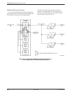
The 6800 Series NMS must send a dial command to
each of the DBM-Vs associated with the digital bridge,
causing each DBM-V to first place a call to its respective
tributary DBM, then switch from Standby to Backup
mode using the Dial Mode (dm) command. (Alternatively,
the same function can be accomplished by the Bkup
command to each DBM-V from the SDCP). Each DBM-V
establishes a call with a DBM, the pair of DBMs
handshake and perform security checks (if so configured),
and go into Dial Backup mode.
Manual DDS Restoration
For a full dial backup session, use the 6800 Series
NMS to restore the control and tributary DSUs to the
DDS network and drop all dial backup calls. Enter release
in the Standby Facility State field and send the Standby
Facility (sf) command to have the control DSU switch the
data path from the bridge to the DSU. Use the dial
command and enter q in the Number to Dial field to have
each DBM-V associated with the digital bridge command
the tributary DSU-DBM to switch back to DDS mode;
both ends then disconnect. Alternatively, address the
control DSU and each of the DBM-Vs via the SDCP; then
issue a DrBU (Drop Backup) command.
Automatic restoration is not possible if the DSU rate
does not equal the DBM rate, and the tributary DSU
should not be configured to drop the backup call and
switch back to the DDS network upon sensing that the
DDS network has been restored because the control DSU
will not automatically switch the data path from the bridge
to the DSU.
* These procedures also apply when the bridge rate is configured for a value other than =DDS.