


Chapter 1 DVS-9000 Functions
156
Setup
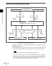
Wiring information input (Wiring)
Input the information which specifies the physical wiring between switcher
and routing switcher or between two routing switchers.
These settings are common to the parallel tally and serial tally.
Tally enable settings (Tally Enable)
Specify the destination to be the reference for tally generation, and make
various settings.
These settings are common to the parallel tally and serial tally.
• Tally Type: Specify the tally type. The tally types which can be specified are
as follows:
When Group Tally is Gp1 to 4: R1, R2, R3, R4, G1, G2, G3, G4
When Group Tally is Gp5 to 8: R5, R6, R7, R8, G5, G6, G7, G8
• Destination: Specify the address and level.
• Tally Enable: Specify the timing at which a tally is enabled.
Enable: Always enabled.
Disable: Always disabled.
Tally Input No.: Follow the tally input status.
Copy (Tally Copy)
Copy the tally information pertaining to a particular source to a different
source.
These settings are common to the parallel tally and serial tally.
Parallel port settings (Parallel Tally)
Make the parallel port settings for output of tally information pertaining to
sources and destinations.
For each of the tally output terminal numbers, specify the tally type, and source
address or destination level and address.
Serial tally settings (Serial Tally)
Make the serial tally settings, including tally type and source address for each
serial tally port.
Simple Connection to MKS-8080/8082 AUX Bus Remote
Panel
To connect the MKS-8080/8082 AUX Bus Remote Panel to a CCP-8000
Center Control Panel using an S-BUS data link requires a BKPF-R70A
Routing Switcher Controller Board or similar primary station and various
settings for connection.
However, using a simple connection, the need for an S-BUS data link primary
station is avoided, and direct connection to the MKS-8080/8082 is possible.