


351Frame Memory Operations
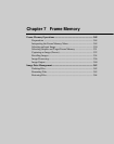
Chapter 7 Frame Memory
1
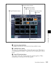
In the auxiliary bus control block, press the AUX delegation button to
which frame memory source bus 1 is allocated, turning it on.
For allocation of buses to the AUX delegation buttons, see “AUX
Delegation Buttons Settings (Aux Assign Menu)” in Chapter 16 (Volume
2).
2
In the auxiliary bus control block cross-point buttons, select the signal to
be used for the input image.
To select a signal with a key or DME effect applied on the frame
memory source bus
In the key control block, press the [FM FEED] button, turning it on.
This automatically assigns the key fill and key source signals being keyed by
the currently selected keyer to frame memory source buses 1 and 2.
When DME is selected on the keyer, the key fill and key source signals to
which a DME effect is applied are assigned.
Selecting Outputs and Target Frame Memory
Selecting outputs (FM) and target frame memory
The signals of frame memory source buses 1 and 2 are used assigned to one of
the pairs of FM1&2, FM3& 4, FM5&6, and FM7&8. The following
description applies to the case of assignment to FM1&2, but the procedures are
similar for the other cases.
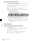
1
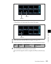
In the Frame Memory menu, press one of VF1 to VF3, and select the
required HF menu.
The current status of frame memory appears in the status area. (See page
349.)
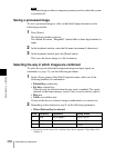
2
If required, press [Pair], to select the FM operation mode (pair mode).
On: Operate on FM1(3, 5, 7) and FM2(4, 6, 8) as a pair.
Off: Operate on FM1(3, 5, 7) and FM2(4, 6, 8) individually.
For more details, see “Pair mode” (page 73).
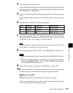
3
In the <Select> group, press [FM1 & FM2] to select it.
This assigns the signals to FM1 and FM2.
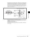
To the right of the target FM selection buttons (see page 349), the FM
output status appears.