3-48 Sun Fire X4100 and Sun Fire X4200 Servers Service Manual • June 2006
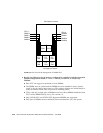
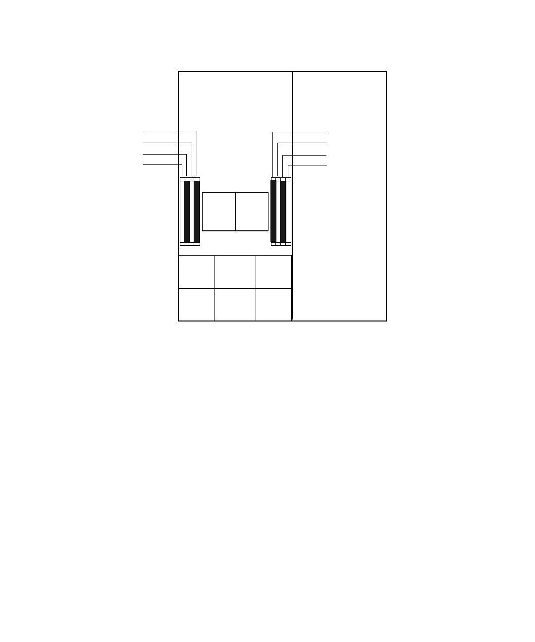
FIGURE 3-43 Sun Fire X4100 Designation of DIMM Slots
5. Review the following list of memory configuration guidelines and the supported
DIMM configurations listed in
TABLE 3-13 before you remove or install any
DIMMs:
■ Each CPU can support a maximum of four DIMMs.
■ The DIMM slots are paired and the DIMMs must be installed in pairs (0 and 1,
2 and 3). See
FIGURE 3-43 and TABLE 3-13. The memory sockets are colored black or
white to indicate which slots are paired by matching colors.
■ CPUs with only a single pair of DIMMs must have those DIMMs installed in that
CPU’s white DIMM slots (0 and 1). See
FIGURE 3-43.
■ Only PC3200 ECC and PC2700 ECC Registered DIMMs are supported.
■ Each pair of DIMMs must be identical (same manufacturer, size, and speed).
FT1
FM0
FT1
FM1
FT1
FM2
FT0
FM0
FT0
FM1
FT0
FM2
CPU1 CPU0
DIMM 0
DIMM 2
DIMM 1
DIMM 3
DIMM 0
DIMM 2
DIMM 1
DIMM 3
Front panel of server
Back panel of server
CPU 1:
CPU 0:


