Chapter 3 Maintaining the Sun Fire X4100 Server 3-15
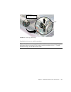
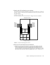
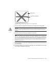
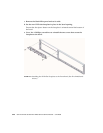
FIGURE 3-12 Required Pattern for Thermal Grease Application
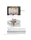
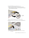
7. Turn the heatsink upright and reinstall the two springs and mounting bolts.
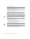
Caution – Avoid moving the heatsink after it has contacted the top of the CPU. Too
much movement could disturb the layer of thermal grease, leading to component
damage.
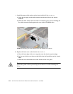
8. Carefully position and align the heatsink over the CPU.
Note – The heatsink is not symmetrical and it must be aligned before you place it on
the CPU. Turn the heatsink so that the “Lever Side” label and arrows imprinted on
the top of the heatsink are pointing to the side of the CPU socket that has the release
lever. Also note that the half of the Sun Microsystems logo imprinted on the top of
the heatsink will create a complete logo when correctly aligned with the adjacent
heatsink. See FIGURE 3-8.
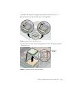
9. Lower the heatsink onto the CPU, aligning the mounting bolts with their holes on
the motherboard.
10. Alternately tighten the two heatsink mounting screws 180-degrees at a time until
each spring is completely compressed.
CPU surface
Lines of thermal grease


