January 2000 © TOSHIBA TEC 4 - 49 FC-22 TROUBLESHOOTING
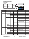
– If they are normal –
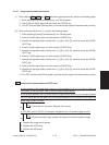
Before starting the color registration control forced performing, a voltage of approxi-
mately 0.7V DC is displayed.
After starting it, the voltage changes to approximately 4.4V DC, and this may drop
instantaneously down to 0.7V DC. (There may be no fluctuations in voltage, depending
on the reaction speed of the digital tester.)
When the color registration control forced performing ends, it returns to a voltage of
approximately 0.7V DC.
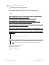
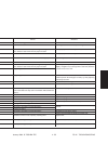
Voltage before color registration control forced performing
DC 0.7V Normal
DC 0V Check if there is any disconnection or short-circuit of harness
between LGC board and color registration sensor, or harness
between LGC board and IMC board. Inspect connector section
(J168 on IMC board, J113 and J114 on LGC board, connector
on color registration sensor).
If there is no abnormality, check color registration sensor.
DC 5V Check if there is any disconnection or short-circuit of harness
between LGC board and color registration sensor. Inspect con-
nector section (J113 and J114 on LGC board, connector on color
registration sensor).
DC 4.4V Check if there is any disconnection or short-circuit of harness
between LGC board and color registration sensor or harness
between LGC board and IMC board. Inspect connector section
(J168 on IMC board, J113 and J114 on LGC board, connector
on color registration sensor)
If there is no abnormality, check color registration sensor.
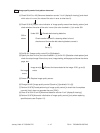
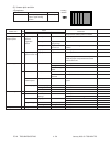
Voltage during color registration control forced performing
Normally DC 4.4V.
Instantaneously
may drop down to
0.7V DC
Normally DC 0.7V
Normally DC 4.4V
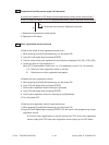
Check if there is any charge defects or exposure errors onto the
photoconductive drum (errors in the laser optical unit). Follow the
next check item 13. and after.
Reading defect of color registration test pattern. Follow the next
check item 13. and after.


