


FC-22 ADJUSTMENT 1 - 22 January 2000 © TOSHIBA TEC
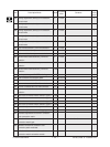
318 Full color Y 67 0~255
319 M 67 0~255
320 C 72 0~255
321 K 67 0~255
326 Y 67 0~255
327 M 67 0~255
328 C 72 0~255
329 K 67 0~255
330 OHP mode Y 61 0~255
331 M 101 0~255
332 C 111 0~255
333 K 141 0~255
334 Y 67 0~255
335 M 67 0~255
336 C 72 0~255
337 K 67 0~255
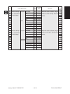
361 Black K 56 0~255
363 K 56 0~255
364 OHP mode K 82 0~255
365
Thick paper2 mode
K 56 0~255
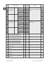
367-0
Y 589 0~5000
367-1
M 589 0~5000
367-2
C 589 0~5000
367-3
K 589 0~5000
368-0
Y 3929 0~5000
368-1
M 3929 0~5000
368-2
C 3929 0~5000
368-3
K 4715 0~5000
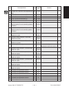
381 Full color Y 72 0~255
382 M 72 0~255
383 C 72 0~255
384 K 72 0~255
385 Black
Thick paper3 mode
K 72 0~255
Acceptable
Operation
Code
Description/Mode
Default
Value
Contents
procedure
group
1
1
1
1
1
1
1
1
1
1
1
1
1
1
1
1
1
1
1
1
4
4
4
4
4
4
4
4
1
1
1
1
1
Transfer bias
output adjustment
Normal paper
mode (Top face)/
thick paper 1
mode
The bias value of the transfer roller
is set. The higher the value, the
larger the transformer output be-
comes. The adjustment value be-
comes effective only when the set-
ting mode (08-400, 401, 409) is 0
(disabled).
Normal paper
mode (Re-
verse face)
Thick paper
2 mode
Normal paper mode
(Top face)/Thick pa-
per 1 mode
Normal paper mode
(Reverse face)
The bias value of the transfer roller
is set. The higher the value, the
larger the transformer output be-
comes. The adjustment value be-
comes effective only when the set-
ting mode (08-400, 401, 409) is 0
(disabled).
Actual output voltage of transfer
roller bias. After replacing the trans-
fer transformer, input the value ac-
cording to the supplementary data
sheet.
Transfer bias out-
put adjustment
Thick paper
3 mode
Transfer bias output
voltage 1 (lower)
Transfer bias output
voltage 2 (upper)