


January 2000 © TOSHIBA TEC 1 - 77 FC-22 ADJUSTMENT
1.16 Adjusting the Scanner Section
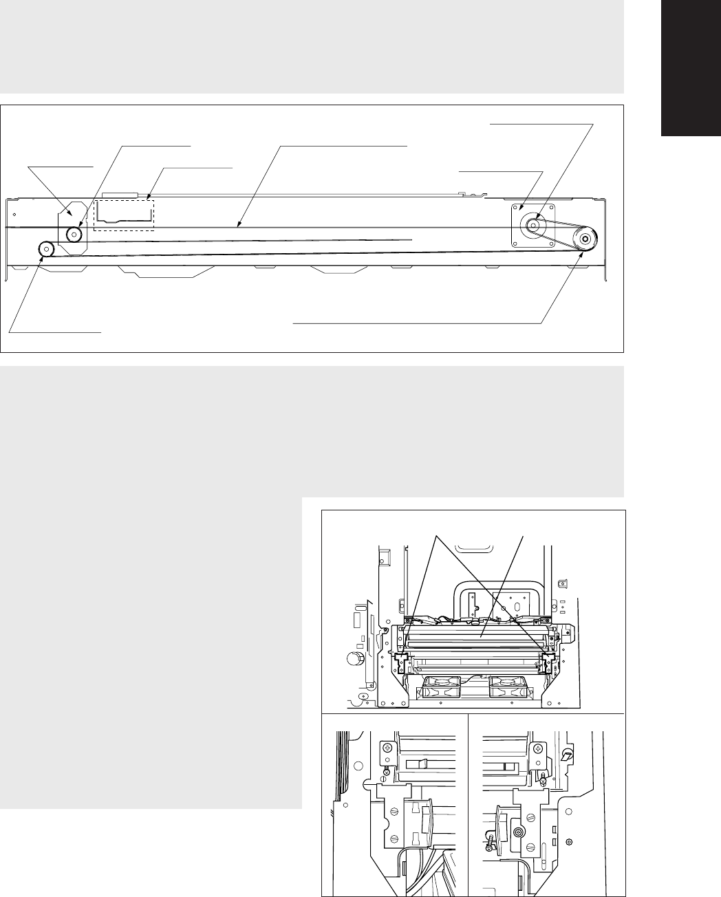
1.16.1 Adjusting the Carriages
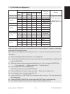
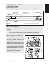
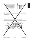
(a) Installing carriage drive wires
When replacing the carriage drive wires with new wires, proceed as illustrated below:
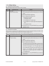
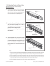
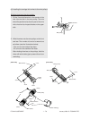
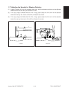
(c) Adjusting the positions of carriages 1 and 2
1. Loosen 2 screws (one each on the front and
rear) which are fixing carriage 1 to the wires,
and another 1 screw (on the front) which are
fixing carriage 2 to the wires.
2. Move carriage 2 to the exit side. Insert the car-
riage jigs into the jig-insertion holes, one each
on the front and rear sides of carriage 2, and
fasten the screw on the front side of carriage 2.
3. While placing the protruding parts of carriage 1
against the carriage jigs, fasten carriage 1 to
the wire on both front and rear sides.
4. Pull out the carriage jigs.
Carriage 1
Front sideRear side
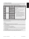
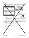
(b) Adjusting the carriage drive wires
Since the wires are applied with proper tension by tension springs, there is no need for tension
adjustment.
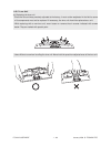
Note:
Check that the wire tension is identical for both front and rear wires and is properly applied.
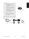
Wire take-up pulley/motor speed reduction pulley
φ
27.37/2GT-Z43
Carriage 2 pulley
φ
20
Carriage drive wire
Scan motor
Motor pulley
2GT-Z26 (26 tooth)
Idler pulley
φ
20
Carriage 2
Carriage 1
Carriage jigs