


4.11 Display Assembly 4 Replacement Procedures
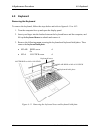
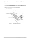
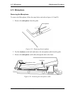
2. Turn the computer face up and open the display panel.
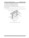
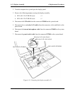
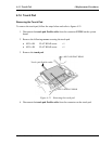
3. Remove the following screws securing the display assembly.
• M2.5×6B FLAT HEAD screw ×3
• M2.5×8B FLAT HEAD screw ×1
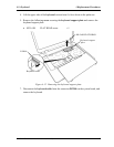
4. Disconnect the LCD cable from the connector PJ5600 on the system board.
5. Disconnect the two wireless LAN cables from the connectors, white and black on the
power board.
6. Disconnect the internal microphone cable from the connector PJ6001 on the system
board.
7. Disconnect the panel switch cable from the connector PJ7004 on the system board.
M2.5×6B FLAT HEAD
PJ5600
PJ6001
PJ7004
Wireless LAN cable (black)
Wireless LAN cable (white)
M2.5×8B FLAT HEAD
Figure 4-16 Removing the display assembly (2)
Satellite M30-35 Maintenance Manual (960-455) 4-33