


4.18 System Board 4 Replacement Procedures
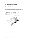
4.18 System Board
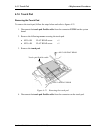
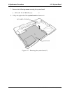
Removing the System Board
To remove the system board, follow the steps below and refer to figures 4-26 and 4-27.
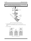
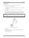
1. Peel off the glass tape and disconnect the RGB cable from the connector PJ5621 on
the system board.
2. Disconnect the speaker cables from the connectors PJ6003 (red) and PJ6004 (blue)
on the system board.
3. Disconnect the USB cable from the connector PJ7003 on the system board.
4. Peel off the glass tapes and disconnect the battery cable from the connector PJ8810
and the network cable from the connector PJ4100on the system board.
5. Disconnect the fan cable from the connector PJ8770 on the system board and the
power cable from the connector CN3 on the power board.
6. Peel off the glass tape and disconnect the USB cable from the connector PJ7005 on
the system board.(VRAM64 only)
Glass tape
Glass tape
RGB cable
Speaker cable (blue)
Speaker cable (red)
USB cable
Fan cable
Battery cable
Network cable
Power cable
Glass tape
Glass tape
USB cable
*Case of the VRAM64 only
Figure 4-26 Removing the system board (1)
Satellite M30-35 Maintenance Manual (960-455) 4-47