


CHAPTER 2 FUNCTIONS & OPERATION
IV. CONTROL SYSTEM
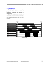
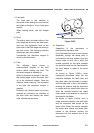
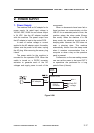
1. Control Circuits
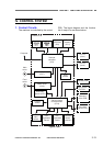
The machine is controlled by the control
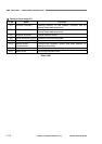
PCB. The block diagram and the function
list of major ICs are shown below.
Control PCB
Serial
EEPROM
(IC8)
Flash
memory
(IC11)
Computer
Motor driver
(IC17)
Door
sensor
Skew sensor
(R) PCB
Ultrasonic
driver PCB
Document
sensor PCB
Flapper
sensor
Document
eject
sensor
Post-
registration
sensor
Pre-
registration
sensor
Ultrasonic
sensor
(receiver)
Sensor control
microcontroller
(IC14)
Operation PCB
Motor driver
(IC16)
Main
motor
Feed
motor
Scanner
controller
(IC6)
CIS unit
(front)
CIS unit
(back)
Document
sensor (LED)
Figure 2-401
COPYRIGHT
©
CANON ELECTRONICS INC. 2011 CANON DR-M140 FIRST EDITION
2-13