


CHAPTER 2 FUNCTIONS & OPERATION
II. READING SYSTEM
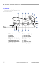
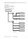
1. Reading Unit
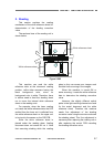
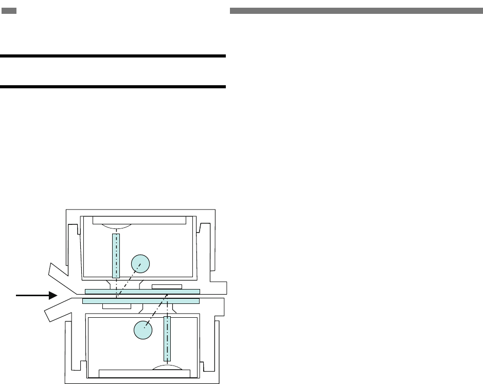
The sectional view of the reading
system is shown below. The upper and
lower reading units have the same
configuration but the different guide shapes.
Upper reading unit
Lower reading unit
Document
Figure 2-201
The upper reading unit reads the front
side of the documents and the lower
reading unit reads the back side of the
documents. This configuration enables the
machine to read both front and back sides
of a document using a single scan.
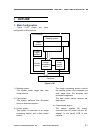
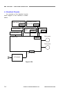
The read image data are sent to the
image processing section of the control
PCB.
To prevent reading speed from
decreasing, the image data is divided into
four and output in parallel.
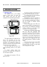
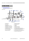
The reading unit consists of CIS unit,
guide, and case.
The CIS unit consists of CIS PCB, lens
array, LED (R/G/B), light guide, and case.
The reading glass and white reference
sheet are mounted on the guide.
Photosensitive pixels are mounted on
the CIS PCB with a density of 600 dpi in a
line. The effective reading width is 219mm,
and the number of effective picture
elements is 5184.
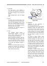
A set of three basic color LEDs, red,
green, and blue (RGB), is mounted only on
the one side. This single-side illumination
causes a shadow on a document, which
may effect on the image data quality.
In the binary or grayscale modes, image
data are read with composite light
generated by lighting the RGB LEDs at the
same time. In the color mode, the LED is
successively lit, and reads image data with
each color. As documents are being fed at
regular speed while image data are read,
the reading positions of RGB are shifted
slightly.
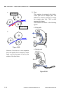
In the color dropout mode, only the LED
of a designated color lights. In the color
emphasis mode, the LED of a color other
than a designated color lights.
2-6
COPYRIGHT
©
CANON ELECTRONICS INC. 2011 CANON DR-M140 FIRST EDITION