CHAPTER 3 DISASSEMBLY & REASSEMBLY
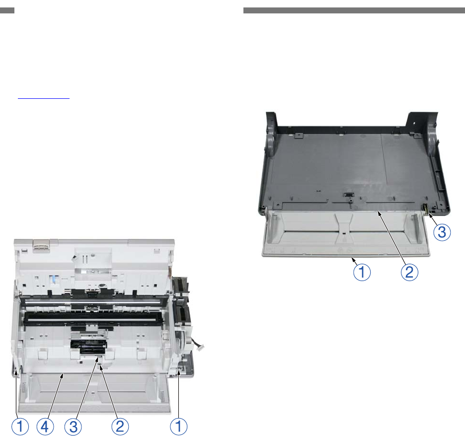
2. Bottom Cover / Feed Tray 3) Remove the document feed tray
{
1
from
the bottom cover
{
2
. The plate spring
{
3
can also be removed.
1) Remove the upper cover.
(Page 3-1)
2) Remove the 2 screws
{
1
(M3,
self-tapping). Then, unhook the fitting
parts
{
3
after removing the screws
{
2
(M3, self-tapping) on the inside of the
retard roller cover, while lifting up the
front side slightly and pulling it towards
you. Remove the main body
{
4
after the
rear side fitting parts come unhooked.
Figure 3-105
Notes on assembling
Assemble the main body from the rear
side, and insert the cables for the
operation PCB in the cable guide, and
ensure that the cables do not get caught
in parts.
Figure 3-104
3-2
COPYRIGHT
©
CANON ELECTRONICS INC. 2011 CANON DR-M140 FIRST EDITION


