


CONTENTS
COPYRIGHT
©
CANON ELECTRONICS INC. 2011 CANON DR-M140 FIRST EDITION
CHAPTER 1
GENERAL DESCRIPTION
I. PRODUCT OUTLINE ..............................1-1
1. Features..............................................1-1
2. Main
Specifications.............................1-2
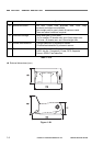
3. Precautions.........................................1-5
II.
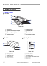
NAME OF PARTS....................................1-6
1. Name of Parts.....................................1-6
III.
USER OPERATION.................................1-7
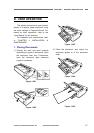
1. Placing Document
s.............................1-7
2. Scanning.............................................1-8
3. Clearing Paper Jams ........................1-10
CHAPTER 2
FUNCTIONS & OPERATION
I. OUTLINE .................................................2-1
1. Main Configuration..............................2-1
2. Feed
Path ...........................................2-2
3. Motor
Drive .........................................2-3
4. Elec
trical Circuits ................................2-4
5. Timing Chart........................................2-5
II. READING SYSTEM.................................2-6
1. Reading Unit.......................................2-6
2. Shading
...............................................2-7
III. FEED SYSTEM .......................................2-8
1. Feeding Mechanism............................2-8
2.
Feed Error Detection ........................ 2-11
IV. CONTROL SYSTEM .............................2-13
1. Control Circuits .................................
2-13
2. Image Processing.............................2-15
V
. POWER SUPPLY ..................................2-17
1. Power Supply....................................
2-17
VI.
LAYOUT OF ELECTRICAL COMPONENTS
.2-18
1. Layout of Electrical Components......2-18
VII. PARTS LAYOUT ON EACH PCB..........2-19
1. Control PCB
......................................2-19
2. Operation PCB..................................2-20
3.
Document Sensor PCB.....................2-20
CHAPTER 3
DISASSEMBLY &
REASSEMBLY
I. EXTERNAL PARTS .................................3-1
1. Upper Cover........................................3-1
2. Bottom
Cover / Feed Tray
...................3-2
3. Document Eject Tray...........................3-3
4. Straight Path Tray
...............................3-3
II. BASE UNIT..............................................3-4
1. Control PCB ........................................3-4
2. Main
Motor ..........................................3-5
3. Feed
Motor..........................................3-6
4. Regis
tration Roller (Drive)...................3-7
5. S
traight Eject Roller (Drive).................3-8
III. UPPER
UNIT .........................................3-10
1. Sensor PCBs ....................................
3-10
2. Ultrasonic Drive PCB ........................3-10
3. Follower
Roller.................................. 3-1
1
4. U-Turn Unit........................................3-12
5. Upper Unit.........................................3-13
IV
. READING UNIT .....................................3-14
1. Upper Reading Unit ..........................3-14
2. Upper Reading Guide .......................3-15
3. Lower
Reading Unit ..........................3-15
4. Lower Reading Guide .......................3-16
CHAPTER 4
INSTALLATION &
MAINTENANCE
I. INSTALLATION........................................4-1
1. System Requirements.........................4-1
2. Checking the Accessories...................4-1
3. Removing the Packing Material ..........4-2
4. Installing the Software
.........................4-2
5. Connecting to a Computer..................4-3
6. Power On ............................................4-3