


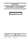


CHAPTER 3 DISASSEMBLY & REASSEMBLY
II. BASE UNIT
1. Control PCB
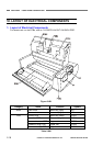
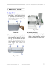
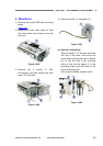
1) Remove the bottom cover and the
document feed tray.
(Page 3-2)
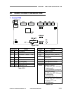
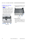
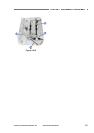
2) Remove the 2 screws
{
1
(M3,
self-tapping) and turn the control PCB
{
2
(with mounting plate) upside-down. Then,
remove the connected connectors.
Figure 3-201
Figure 3-202
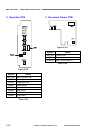
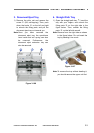
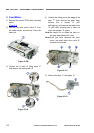
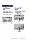
3) Remove the 6 screws
{
1
(M3xL4) and
remove the control PCB
{
2
from the
mounting plate.
Figure 3-203
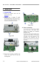
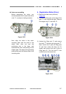
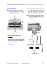
Notes on assembling
You should insert the connector straight
and all the way in. Be careful when
handling the reading unit connector
because it is thin.
Furthermore, although the lengths of the
upper and lower cables of the reading
unit differ to suit the positions of the
connectors, the connectors are the
same, and you should not connect them
incorrectly.
Lower
(J111)
Upper
(J110)
Figure 3-204
3-4
COPYRIGHT
©
CANON ELECTRONICS INC. 2011 CANON DR-M140 FIRST EDITION