


CHAPTER 3 DISASSEMBLY & REASSEMBLY
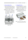
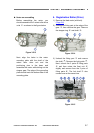
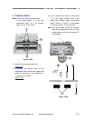
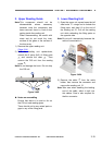
3. Follower Roller
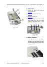
3) If you unhook the 2 pairs of fitting parts
{
1
on the target follower roller at the
same time, follower roller on the back
side (2 rollers
{
2
, shaft
{
3
, and stopper
{
4
) and the spring
{
5
are removed.
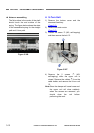
Note: There are 3 sets of follower rollers.
In the figure below,
{
1
is for the
registration roller,
{
2
is for straight
path, and
{
3
is for U-turn.
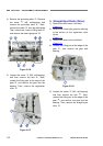
Note: The figure below shows the follower
roller for the registration roller. For the
straight path and U-turn, the spring
{
6
is connected.
Figure 3-304
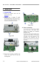
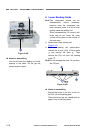
1) Remo
ve the document eject tray.
(Page 3-3)
2) To remove the follower roller for the
registration roller, remove the upper light
guide by referring to the procedure in
"Ultrasonic Drive PCB".
(Page 3-10)
Figure 3-305
COPYRIGHT
©
CANON ELECTRONICS INC. 2011 CANON DR-M140 FIRST EDITION
3-11