


CHAPTER 5 TROUBLESHOOTING
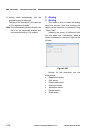
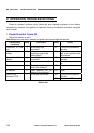
3. Scaling Rate Control
This mode adjusts the scale parameter
to make the length of the image in the feed
direction correct. It performs adjustment
using the front side image. The same values
are applied to the reverse side image as the
front side.
If the image leading edge position is
different, perform registration adjustment
first.
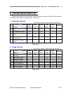
Types
There are three types of scale parameter
adjustment.
1) Factory Scale for separate mode
2) Factory Scale for none separate mode
3) User Scale
Since the feed method differs between
separate and none separate mode, a
slight difference occurs in the scale
parameter and the individual scale
parameters are set when shipped from
the factory.
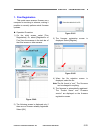
Furthermore, there is a user scale
parameter to enable the user to re-adjust
after the product ships. The setting can
be configured from the “Utility/USB
Properties/Maintenance” user operating
screen. That value is linked with the
“User Scale” in this mode. Note that the
user value is displayed to one decimal
place with the value rounded.
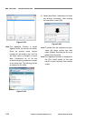
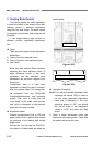
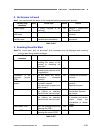
Adjustment sheet
Prepare a single sheet of A4 or LTR size
paper printed with a pattern that makes
the positions of the leading and trailing
edges clear.
Service tool: You can use the TKM-0271
test sheet or a hand-made test sheet as
shown below.
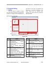
TKM-0271
Figure 5-255
Leading edge of the hand-made sheet
Figure 5-256
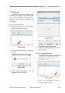
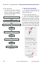
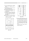
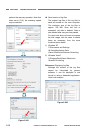
Operation Procedure
Note: If you adjust the scale parameter after
replacing the control PCB or want to
set the scale parameter adjustment
value that is displayed in the user
operating screen to “0.0”, you should
first set all three of the adjustment
values to “0.00” and select the [Set]
button.
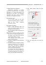
1) Place a single adjustment sheet and
adjust the document guides. Place with
the pattern surface at the front.
5-32
COPYRIGHT
©
CANON ELECTRONICS INC. 2011 CANON DR-M140 FIRST EDITION