


CHAPTER 3 DISASSEMBLY & REASSEMBLY
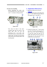
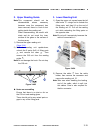
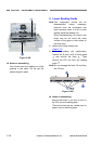
4. U-Turn Unit Notes on assembling
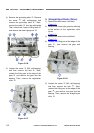
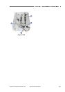
The flat surface in the center of the shaft
should touch the end surface of the
spring. The figure below shows the state
of the assembled spring for the straight
path and U-turn path.
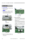
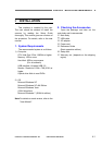
1) Remove the bottom cover and the
document feed tray.
(Page 3-2)
2) Remove the main motor.
(Page 3-5)
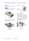
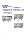
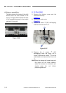
3) Loosen the screw
{
1
(M3, self-tapping)
and then remove the belt
{
2
.
Figure 3-306
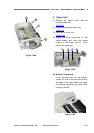
Figure 3-307
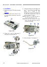
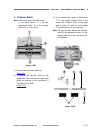
4) Remove the 2 screws
{
1
(M3,
self-tapping) while the upper unit is
closed. Remove the cables
{
2
from the
cable holder, and remove the U-turn unit
{
3
.
Note: Since the damper will come loose and
the upper unit will close suddenly
when the screws are removed, you
should close the unit before
performing the work.
3-12
COPYRIGHT
©
CANON ELECTRONICS INC. 2011 CANON DR-M140 FIRST EDITION