


CHAPTER 2 FUNCTIONS & OPERATION
VI. LAYOUT OF ELECTRICAL COMPONENTS
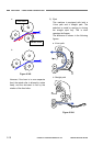
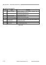
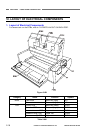
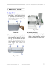
1. Layout of Electrical Components
For sensors etc. on the PCBs, refer to “VII.PARTS LAYOUT ON EACH PCB”.
Figure 2-601
Category Name Location Symbol
Feed motor Base unit (right) M1 Motor
Main motor Base unit (right) M2
Control PCB Base unit (lower) PCB1
Operation PCB Base unit (right) PCB2
Document sensor PCB Upper unit PCB3
Ultrasonic drive PCB Upper unit PCB4
PCB
Skew sensor (R) PCB Upper unit PCB5
Table 2-601
2-18
COPYRIGHT
©
CANON ELECTRONICS INC. 2011 CANON DR-M140 FIRST EDITION