


CHAPTER 1 GENERAL DESCRIPTION
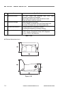
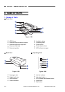
II. NAME OF PARTS
1. Names of Parts
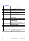
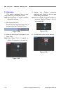
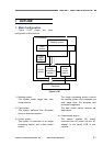
Front View
Figure 1-201
{
1
OPEN lever
{
2
Document eject extension support
{
3
Document eject tray/Upper unit
{
4
Document feed tray
{
5
Document guides
{
6
Ventilation holes
{
7
Operating panel
{
8
Power button
{
9
Feed selection lever
{
10
LED indicator (orange)
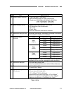
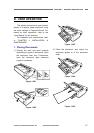
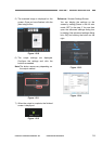
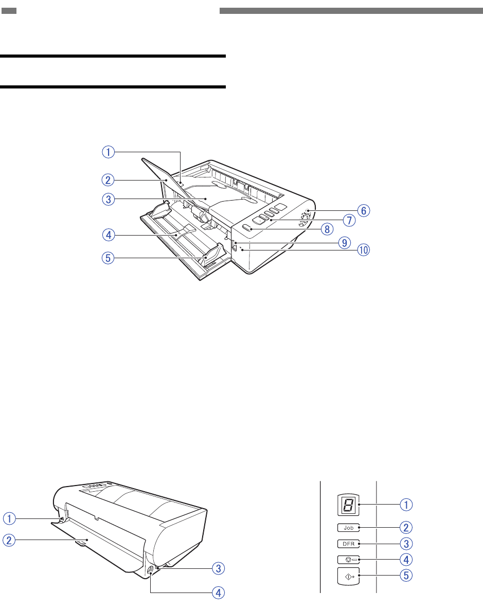
Back View Operating Panel
Figure 1-202 Figure 1-203
{
1
Kensington slot
{
2
Straight path tray
{
3
USB connector
{
4
Power connector
{
1
Job No. indicator
{
2
Job select button
{
3
DFR (Double Feed Release) button
{
4
Stop button
{
5
Start button
1-6
COPYRIGHT
©
CANON ELECTRONICS INC. 2011 CANON DR-M140 FIRST EDITION