


84
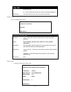
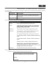
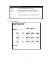
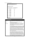
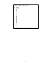
To display bandwidth control settings:
DES-3550:4#show bandwidth_control 1-10
Command: show bandwidth_control 1-10
Bandwidth Control Table
Port RX Rate (Mbit/sec) TX_RATE (Mbit/sec)
---- ------------------------ ----------------------
1:1 no_limit 10
1:2 no_limit 10
1:3 no_limit 10
1:4 no_limit 10
1:5 no_limit 10
1:6 no_limit 10
1:7 no_limit 10
1:8 no_limit 10
1:9 no_limit 10
1:10 no_limit 10
DES-3550:4#
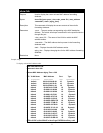
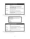
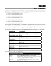
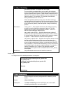
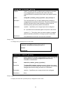
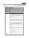
config scheduling
Purpose Used to configure the traffic scheduling mechanism for each COS
queue.
Syntax
config scheduling <class_id 0-3> [max_packet <value 0-
255>|max_latency <value 0-255>]
Description The switch contains 4 hardware priority queues. Incoming packets
must be mapped to one of these four queues. This command is
used to specify the rotation by which these four hardware priority
queues are emptied.
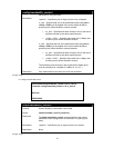
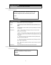
The switch’s default (if the config scheduling command is not used,
or if the config scheduling command is entered with both max_packet
and max_latency parameters are set to 0) is to empty the 4 hardware
priority queues in order − from the highest priority queue (hardware
queue 3) to the lowest priority queue (hardware queue 0). Each
hardware queue will transmit all of the packets in its buffer before
allowing the next lower priority queue to transmit its packets. When
the lowest hardware priority queue has finished transmitting all of its
packets, the highest hardware priority queue can again transmit any
packets it may have received.
The max_packets
parameter allows you to specify the maximum
number of packets a given hardware priority queue can transmit
before allowing the next lowest hardware priority queue to begin
transmitting its packets. A value between 0 and 255 can be specified.
For example, if a value of 3 is specified, then the highest hardware
priority queue (number 3) will be allowed to transmit 3 packets − then
the next lowest hardware priority queue (number 2) will be allowed to
transmit 3 packets, and so on, until all of the queues have