


NGA-2000 System Calibration
Supplement - 4 NGA 2000 90003482(2) [NGA-e (MLT-Software 3.2.X)] 07/98
2 Valves for system calibration
Before using the system calibration we have to put together the required valve pool. There
are in principle three types of I/O modules supporting this:
• DIO - 24 digital outputs / 8 digital inputs (max. 4 DIO modules per platform or 2 per
MLT/TFID analyzer)
• SIO - 3 digital outputs (max. 1 SIO module per CM)
• [CVU - - 4 digital outputs (max. 4 modules per CM)]
Software supports up to 32 system valves. SIO and DIO are available, the control valve unit
(CVU) is in progress.
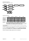
2.1 Assigning an output port to a system valve
Assigning of an output can be accomplished by using the menus for selected output module
(DIO, SIO or CVU).
There we have to select the NGA Control Module as the Source Module. Control module
then provides the signals for system valve V1...V32.
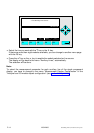
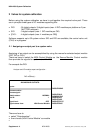
For example the DIO:
DIOOUTNUMC
DIOOUTINVC
DIOMODSTAC
DIOSLOTIDC
DIOOUTSIGC
DIOOUTSTATC
DIOOUTSRCC
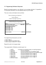
There we have to
• select "Outputnumber"
• then choose „NGA Control Module“ as module
•
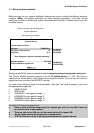
Analyzer and I/O-module expert configuration...
↓
↓
DIO module(s)...
- DIO-MODULE OUTPUTS-
Inputs...
Choose module...
Choose signal...
Module status: NORMAL
Slot ID: 1
Signal level: OFF
Signal comes from: NGA Control Module