


Confidential
EPSON
TITLE
SHEET
REVISION
NO.
SHEETNEXT
L
TM-U210 series
Specification
(STANDARD)
1213
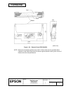
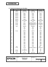
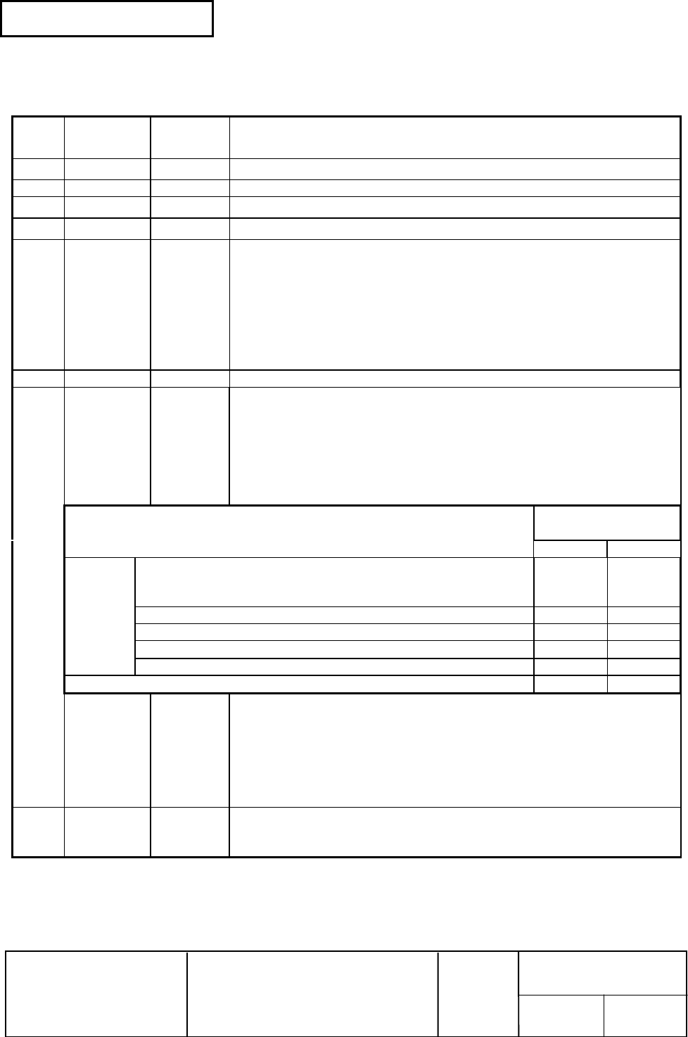
2.1.1.3 Interface connector terminal assignments and signal functions
Table 2.1.1 Interface Pin Assignments and Functions
Pin
No.
Signal
Name
Signal
Direction
Function
1
FG – Frame ground
2 TXD Output Transmit data
3
RXD Input Receive data
4 RTS Output
Same as DTR signal (same as pin 20)
6 DSR Input Indicates whether the host can receive data. SPACE indicates that the
host can receive data, and MARK indicates that the host cannot
receive data. When DTR/DSR control is selected, the printer transmits
data after checking this signal (except when data is sent by DLE EOT,
GS a). When XON/XOFF control is selected, the printer does not
check this signal. Changing the DIP switch setting enables this signal
to be used as a reset signal for the printer The printer is reset when
the signal remains MARK for 1 ms or more.
7 SG – Signal ground
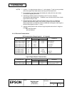
20 DTR Output 1) When DTR/DSR control is selected, this signal indicates whether
the printer is BUSY.
SPACE indicates that the printer is READY to receive data, and
MARK indicates that the printer is BUSY.
DIP switch 1-8 switches conditions for BUSY.
The BUSY (MARK) condition is changed using DIP switch 1-8 as
follows:
Printer Status
Dip Switch 1-8
Status
ON OFF
Off-line 1) The period from power-on (or initialization of the
mechanism due to resetting through the interface) until
the printer is ready to receive data.
BUSY BUSY
2) During the self-test BUSY BUSY
3) During paper feeding using the FEED button ---- BUSY
4) When the printer stops due to a paper-end (ESC c 4).
---- BUSY
5) During an error condition ---- BUSY
6) When the receive buffer is full (*1) BUSY BUSY
2) When XON/XOFF control is selected, this signal indicates whether
the printer is properly connected and is ready to receive data.
SPACE indicates that the printer is properly connected and is
ready to receive data. This signal is always SPACE except during
the following periods:
• From power-on until the printer is ready to receive data.
• During the self-test.
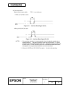
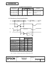
25 INIT Output Changing the DIP switch setting enables this signal to be used as a
reset signal for the printer. The printer is reset when the signal
remains SPACE for 1 ms or more.