


Confidential
EPSON
TITLE
SHEET
REVISION
NO.
SHEETNEXT
L
TM-U210 series
Specification
(STANDARD)
1415
2.1.1.6 Notes on setting DIP switch 1-8 to on
(1) The printer mechanism stops but does not become BUSY in the following cases:
• When an error occurs.
• When the printer stops printing due to a paper-end.
• When paper is fed using the feed button.
(2) When handshaking with the printer while using this switch setting, make sure to monitor the
printer with the GS a command and the ASB function.
With this switch setting, the default value of the GS a command n is 2. This automatically
transmits the printer status, depending on online/offline changes.
(3) When using the DLE EOT or DLE ENQ command, make sure that the receive buffer does not
become full.
• Notes on using a host that cannot transmit data when the printer is BUSY:
If an error occurs when the receive buffer is full and the printer is BUSY, the DLE EOT
and DLE ENQ commands cannot be used.
• Notes on using a host that can transmit data when the printer is BUSY:
If a DLE EOT or DLE ENQ command is used while sending bit-image data, and the
receive buffer-full state is encountered during transmission of the data, the DLE EOT or
DLE ENQ is processed as bit-image data.
In addition, the data transmitted during the receive buffer-full state may be lost.
Example:
Set the receive buffer to 1KB, and check the status with GS r for each line of printing
transmitted. Make sure the data for printing each line does not cause the printer to enter the
receive buffer-full state.
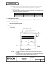
2.1.1.7 Notes on resetting the printer using the interface
The printer can be reset through the interface (pins 6 or 25) by changing the DIP switch settings
accordingly (Refer to Table 2.1.3).
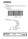
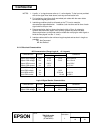
Table 2.1.3 Switching of the Reset Condition
Pin No. DIP Switch Reset Condition
Pin 6 (DSR) DSW 2-7: ON MARK input
Pin 25 (INIT) DSW 2-8: ON SPACE or TTL-HIGH level voltage signal input
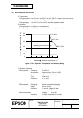
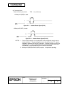
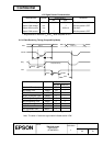
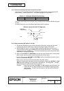
To reset the printer, the conditions given below must be satisfied:
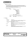
<DC characteristics>
Table 2.1.4 DC Characteristics of the Reset Condition
Item Symbol Pin 6 (DSR) Pin 25 (INIT)
Input HIGH level voltage VIH +3 to +15 V +2 to + 15 V
Input LOW level voltage VIL -15 to -3 V -15 to + 0.8 V
Input HIGH level current IIH 5 mA (maximum) 1 mA (maximum)
Input LOW level current IIL -5.3 mA (maximum) -2 mA (maximum)
Input impedance RIN
3 kΩ (minimum)