Confidential
EPSON
TITLE
SHEET
REVISION
NO.
SHEETNEXT
L
TM-U210 series
Specification
(STANDARD)
2223
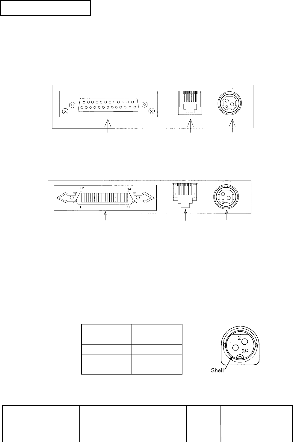
2.2 Connectors
2.2.1 Interface connectors
Refer to Section 2.1, Interface Specifications.
(1) RS-232 serial interface specification
Power Supply
Connector
Drawer Kick-out
Connector
Interface Connecto
r
61
1
14
13
25
Figure 2.2.1 Serial Connector Panel Diagram
(2) IEEE 1284 Parallel interface specification
Power Supply
Connector
Drawer Kick-out
Connector
Interface Connector
Figure 2.2.2 Parallel Connector Panel Diagram
2.2.2 Power supply connector
This connector is used to connect the printer to an external power source.
1) Pin assignments: Refer to Table 2.2.1.
2) Model (printer side): Hosiden TCS7960-532010 (or equivalent)
3) Model (host side): Hosiden TCP8927-631100 (or equivalent)
or TCP8927-531100 (or equivalent)
Table 2.2.1 Power Supply Connector Pin Assignments
Pin Number Signal Name
1 + Power source
2 GND
3 NC
Shell FG
NOTE: Be sure to ground the frame ground (FG) screw on the board at the bottom of the unit.
Figure 2.2.3 Power Supply Connector
1
3
2
1
3
2


