


Exatron 3000B
www.exatron.com 2-5 Chapter 2 Installation
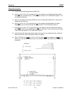
1.
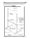
Using six #1/4 - 20 x 1.75" long bolts and six
lock washers, attach the two uprights to the base
plate. Note the location of the small holes in the base in relation to the uprights.
2.
Tighten all six bolts.
3.
Locate the two riser bars (#3000-041) and the rigid support bar (#3000-034.) Using four #1/4
- 20 x 2.75" long bolts, four block washers and four #1/4 - 20 hex nuts, attach the risers and
the rigid support bar to the uprights by inserting the bolts through the upright, through the riser
and then through the holes in the rigid support bar. The large holes in the riser should be at
the top. Assemble the riser bar in the lowest position initially and then adjust its height as
needed. Place lock washers and nuts on all bolts. Do not tighten the bolts yet.
4.
Place the handler power supply on the base (#3000-032.) Insert the rubber feet on the power
supply into the pre-cut holes in the base.
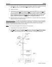
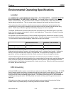
Please refer to Figure B. The FRED may be assembled with either of two different pivot points depending
upon your application. The hardware remains the same in both cases. Type A pivot is recommended for
handlers using cable-type test contact interface. Type B pivot is recommended for zero test head
interfaces, or when docking the handler to a manipulator.
NOTE: The maximum slide angle for PLCC devices is 45
°
from vertical.
1.
Locate the two blue pivot plates (#3000-035.)
2.
Using two #3/8 x 16 x 2.75" long bolts, four
#3/8 x 16 x 1.75" long bolts, six #3/8 lock washers
and six #3/8 x 16 hex nuts, attach the pivot plates to the riser bars according to the pivot point
selected. Place lock washers and nuts on all six #3/8 bolts. Do not tighten the bolts yet.