Exatron 3000B
www.exatron.com 5-14 Chapter 5 Diagnostics
;
;;
;
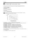
ALL MOTOR CHECK: Shuttle Motor Check
_______________________________________________________
This diagnostic tests input port C4, output port C4, C9, located on PCB #5000-397, PAL 397-3, U7.
TO ENTER THIS CHECK:
Handler displays
DIAGNOSTICS
Press the
[4]
key.
Handler displays
ALL MOTOR CHK
Press the
[1]
key.
Handler displays
SORT MOTOR CHK
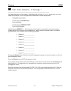
NOTE: The handler's output cover LEDs will indicate the current location of the shuttle. The correct
pattern for an empty shuttle at each output bin is as follows:
LED 1 2 3 4 5 6 7 8
BIN
1
{
}
{
{
{
{
{
{
2
}
{
}
{
{
{
{
{
3
{
}
{
}
{
{
{
{
4
{
{
}
{
}
{
{
{
5
{
{
{
}
{
}
{
{
6
{
{
{
{
}
{
}
{
7
{
{
{
{
{
}
{
}
8
{
{
{
{
{
{
}
{
}
Indicates flashing LED
{
Indicates LED turned off
Press the
[1]
key: "1 LEFT STEP." The Shuttle will move one tube to the left.
Press the
[2]
key: the handler will display the current motor settings in RAM. This display is helpful when
trying to increase the motor's speed.
Press the
[3]
key: "1 RIGHT STEP." The Shuttle will move one tube to the right.
Press the
[4]
key: "2 LEFT STEPS." The Shuttle will move two tubes to the left.
Press the
[6]
key: "2 RIGHT STEPS." The Shuttle will move two tubes to the right.
Press the
[7]
key: "JOG LEFT." The Shuttle will move one step to the left, about .006".
Press the
[8]
key: the shuttle will try to automatically center itself at Home bin #5.
Press the
[9]
key: "JOG RIGHT." The Shuttle will move one step to the right, about .006".
Press the
[0]
key: "MOTOR OFF." The Output Sort Motor is now off.
Pressing the
[Clear]
button will flash the terminal's displayed message to confirm the handler is still in this
specific diagnostic check.
Press the
[Enter]
button to EXIT this diagnostic check.


