


Exatron 3000B
www.exatron.com 3-9 Chapter 3 Interface Info
Handler Port Interface
T
HE
H
ANDLER
P
ORT INTERFACE USES SIMPLE
TTL-
COMPATIBLE SIGNALS TO CONTROL THE HANDLER
. This
parallel port interface utilizes the 24 pin “D” connector on the side of the handler. It has been designed
to be compatible with “MCT-type” tester control interfaces.
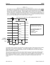
The H
ANDLER
P
ORT
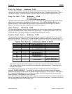
interface uses the addresses 00C0 through 00C7 for tester sort to output bin and
address 00BC for double test on/off selection. Please refer to the General Interface RAM Selections
section at the beginning of this chapter for further details.
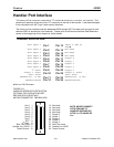
Handler Port Pin Out:
Sort Input 1
Pin 1 Pin 13
Input 9, End of
Test
Sort Input 2
Pin 2 Pin 14
Not Used
Sort Input 3
Pin 3 Pin 15
Not Used
Sort Input 4
Pin 4 Pin 16
Not Used
Sort Input 5
Pin 5 Pin 17
Output 8
Sort Input 6
Pin 6 Pin 18
Output 7
Sort Input 7
Pin 7 Pin 19
Output 6
Sort Input 8
Pin 8 Pin 20
Output 5
2
nd
Start
Pin 9 Pin 22
Output 4
Output 1, Start
Test: Pulse
Pin 10 Pin 22
Output 2, Start
Test: Level
Handler
Vcc, +5 VDC
Pin 11 Pin 23
Handler
Vcc, +5 VDC
Handler
Ground
Pin 12 Pin 24
Handler
Ground
S
PECIAL
PAL R
EQUIRED
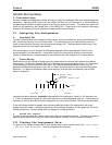
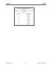
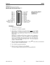
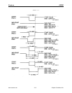
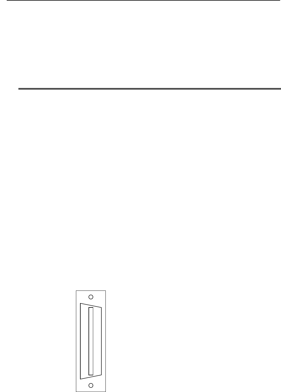
FIGURE 3-1
A
HANDLER INTERFACE PORTS DETAIL
OPTIONAL OPTO ISOLATION PORT
SEE 5000-D76 FOR DETAILS
MATING CONNECTOR T&B #609-2030
Sort 1 1
Sort 2 2
Sort 3 3
Sort 4 4
Sort 5 5
Sort 6 6
Sort 7 7
EOT 8
2
nd
Start 9
Start Test Pulse 10
Handler Vcc +5VDC 11
Tester Ground 12
13 Not Used
14 Not Used
15 Not Used
16 Not Used
17 Output 8
18 Output 7
19 Output 6
20 Output 5
21 Output 4
22 Start Test Level
23 Handler Vcc+5VDC
24 Tester Ground
NOTE: NEVER CONNECT
OPTO GROUND TO
HANDLER GROUND OR
OPTO Vcc TO HANDLER
V
cc