Exatron 3000B
www.exatron.com 4-1 Chapter 4 Handler Setup
Chapter 4 Handler Set Up
Overview
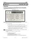
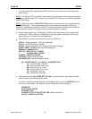
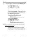
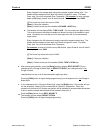
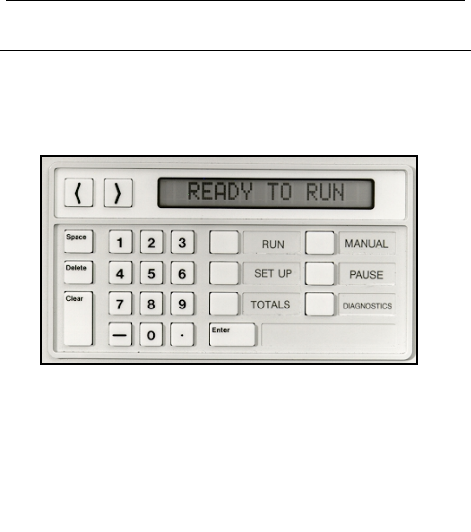
The intelligent front panel microterminal of the Model 3000B handler controller allows jobs to be set up
and running in minutes.
Set Up
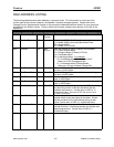
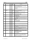
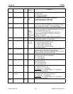
consists of making handler operation selections regarding
Package
Type
,
Interface Type
,
Output Tube Full Count
,
Plunge Depth
(for plunge-to-board changeover kits)
and
Stop On Fail
features for the job you wish to run.
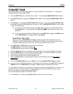
MICROTERMINAL DISPLAY
Please read and understand this entire User's Manual before attempting to Set Up your E
XATRON
handler.
After you have done so, use the following procedure to begin regular production.
1.
First, verify the following:
A.
Handler is plugged into power outlet with working EARTH ground connection.
B.
If the type of changeover kit requires it, the handler is connected to a dry air pressure
supply of 80 PSI, +/-3 PSI. The air supply must be free from moisture and oil.
C.
The programmer/tester is properly docked to the back of the handler. Verify that the
programmer/tester is installed with the correct "Pin 1" orientation.
NOTE: Do not run the handler with the programmer/tester undocked. If you do, the handler will release
parts out of the test site onto the floor.
2.
Verify that the proper changeover kit is installed on the handler.
Check:
A.
Octoloader input tube holder plate.
B.
Main test site rail assembly.
C.
Correct size plunger bar. (Plunge-to-board change kits.)
D.
Shuttle assembly. (May be insert only.)
E.
Proper extruded aluminum output tubes or output tube holder with plastic tubes.


