Exatron 3000B
www.exatron.com 2-7 Chapter 2 Installation
UNPACKING HOT RAIL HANDLERS:
MODEL 3010B
Tools required: One standard flat-bladed screwdriver
One Phillips head screwdriver
The Model 3010B Hot Rail is shipped in at least three boxes. The largest box, 46" x 23" x 32" contains the
handler/hot rail as an assembled unit. The FRED box is 5" x 33" x 24" and contains the Free Rolling
Exatron Dolly frame. The third box, 20" x 18" x 18", contains two power supplies. A fourth box may be
included in your shipment containing spare parts or additional handler options. Open these boxes in the
order listed below so that loose parts do not become mixed or misplaced.
UNPACKING THE POWER SUPPLY
The power supply is shipped in a separate 20" x 18" x 18" cardboard box.
Open the box with the "
DELICATE INSTRUMENT
" label side up and remove the top internal box
containing handler peripherals, such as: Octoloader Plate, Air Regulator, Shuttle, User's Manual and
Power Cords. Set these items aside.
Open the bottom internal box and remove the power supply using both hands.
Set the power
supply aside and return the packing material to the empty box. The shipping carton should now be ready
for storage - DO NOT DISCARD! Proceed with the unpacking/assembly instructions.
UNPACKING THE FRED/ENVIRONMENTAL ASSEMBLY
Tools required: One standard flat-bladed screwdriver
One Phillips head screwdriver
Size 6 Allen wrench
Open the fred shipping box and remove all parts of the metal fred.
Inside the box you will find one
additional set of FRED assembly instructions, Detail Figures A, B and C, and one FRED parts list.
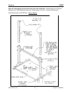
Assemble the base of the FRED first. Refer to Figure A.
1.
Using six #1/4 - 20 x 1.75" long bolts and six
lock washers, attach the two uprights to
the base plate. Note the location of the small holes in the base in relation to the
uprights.
2.
Tighten all six bolts.
3.
Locate the two riser bars (#3000-041) and the rigid support bar (#3000-034.) Using
four #1/4 - 20 x 2.75" long bolts, four
block washers and four #1/4 - 20 hex nuts,
attach the risers and the rigid support bar to the uprights by inserting the bolts through
the upright, through the riser and then through the holes in the rigid support bar. The
large holes in the riser should be at the top. Assemble the riser bar in the lowest
position initially and then adjust its height as needed. place lock washers and nuts on
all bolts. Do not tighten the bolts yet.
4.
Place the handler power supply on the base (#3000-032.) Insert the rubber feet on
the power supply into the pre-cut holes in the base.
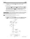
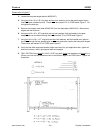
Please refer to Figure B. The FRED may be assembled with either of two different pivot points depending
upon your application. The hardware remains the same in both cases. Type A pivot is recommended for
handlers using cable-type test contact interface. Type B pivot is recommended for zero test head
interfaces, or when docking the handler to a manipulator.
NOTE: The maximum slide angle for PLCC devices is 45
°
from vertical.


