Exatron 3000B
www.exatron.com 3-16 Chapter 3 Interface Info
Exatron Super
The Exatron Super interface allows for computer control of the handler, tester/programmer, and
label/laser marker as a complete system. This interface uses the handler’s RS-232 Control Port to
communicate with the controlling computer running Exatron E5000 laser software or Exatron Label Maker
software. The actual connection to the computer is usually COM1, COM3, or the first port on the
Digiboard I/O box. This may vary depending upon your handler's configuration.
All aspects of production are controlled by the computer carrying out instructions as they are defined in a
file called a "Job." Job files may be created, edited and saved as desired by the operator.
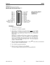
All serial connections are 25 pin to 25 pin “straight through.” If a special cable is needed for your
programmer/tester, please provide Exatron with the pin out configuration or the cable itself, so that we
may furnish compatible interface hardware.
The communications settings are fixed in the firmware at
9600 Baud, No Parity, 8 Data Bits, 1 Stop
. All
serial devices connected to the Exatron controlling computer should be so configured.
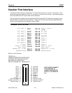
The connector on the handler is a 25 pin RS-232-type “D” connector with female pins. The mating
connector on the interface cable must use male pins. The RS-232 side panel port uses the following pins:
Pin
1
=
GROUND
Pin
2
=
RECEIVE
;
input to handler
Pin
3
=
SEND
;
output from handler
Pin
7
=
GROUND
Typically this cable is wired one to one (1 : 1) to the RS-232 port on the back of a PC using a 25 pin RS-
232 connector. If your PC uses a 9 pin RS-232 port, then, typically use a straight through interface cable.
Laser Only Kit:
[model 5000 only.]
This special interface is a sub-set of the Exatron super interface. It is intended to be used with
change
over kits which do not have a test site, i.e. kits which are for laser marking only. Please refer to the
EXATRON
SUPER
section above for additional information on how to use this interface. As with the
EXATRON
SUPER
interface, the communications settings are fixed in the firmware at
9600 baud, no parity, 8 data
bits, 1 stop.
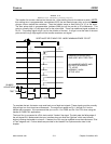
The following address in the handler's battery backed-up RAM may be edited to fine tune the handler for
your specific programmer/tester and sorting requirements. This address is not part of the standard power-
up selections and
may be modified only by “Changing The RAM,”
as described in the Handler Set-Up
Chapter of this manual.
REMOTE GO: ADDRESS 0099
00 = On
FF = Off
This address must be set to On for the controlling computer to have access to the handler's RAM. If this
address is not set properly, the handler will display the message:
WAITING FOR PC
.


