


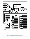
Clock Module
MCF52211 ColdFire® Integrated Microcontroller Reference Manual, Rev. 2
6-12 Freescale Semiconductor
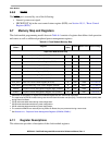
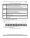
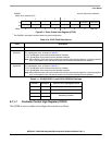
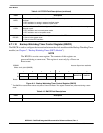
6.7.1.5 Clock Control High Register (CCHR)
The CCHR sets the pre-division factor, which divides down the PLL input clock by 1 (CCHR[2:0] = 000)
to 8 (CCHR[2:0] =111). This allows an external oscillator or crystal of more than 10 MHz to be used with
the PLL. The division factor should be set to generate an input clock for the PLL above 1 MHz and below
10 MHz. When CCHR[2:0] are changed or the PLL is disabled in stop mode, the PLL loses lock.
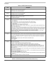
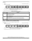
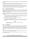
6.7.1.6 Clock Control Low Register (CCLR)
The CCLR selects the clock source for the PLL input/bypass clock. The two possible sources are the
external oscillator (in external crystal or external oscillator mode) and the relaxation oscillator. When
switching clock sources, the module ensures that the changeover does not cause spurious glitches in the
system clock, and that the crystal and the relaxation oscillator remain enabled for the duration of the
changeover.
When switching the clock source to the relaxation oscillator, OCHR[OCOEN] should be set before
OSCSEL is set. Similarly, when switching the clock source to the external oscillator, OCLR[OSCEN]
should be set before OSCSEL is cleared.
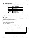
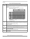
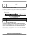
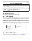
Table 6-8. LPDR Field Descriptions
Field Description
7–4 Reserved, should be cleared.
3–0
LPD
Low-Power Divider. This field is used to divide down the system clock by a factor of 2
LPD
.
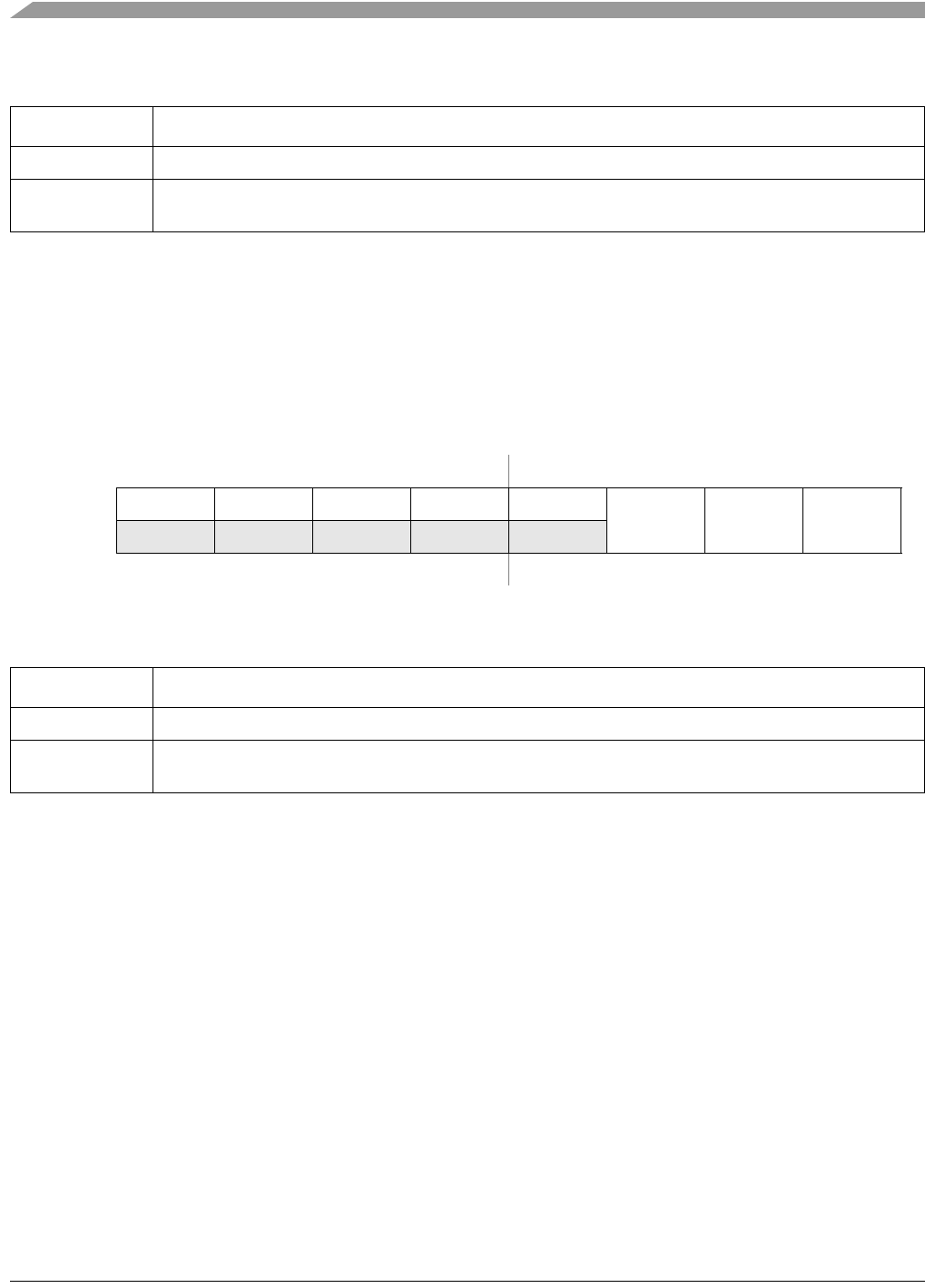
IPSBAR
Offset: 0x12_0008 (CCHR)
Access: Supervisor read/write
76543210
R — — — — —
CCHR2 CCHR1 CCHR0
W
Reset:00000101
Figure 6-6. Clock Control High Register (CCHR)
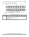
Table 6-9. CCHR Field Descriptions
Field Description
7–3 Reserved, should be cleared.
2–0
CCHR
Clock Control High Register. This field is used to divide down the system clock by a factor of CCHR+1.