


Pulse-Width Modulation (PWM) Module
MCF52211 ColdFire® Integrated Microcontroller Reference Manual, Rev. 2
Freescale Semiconductor 27-13
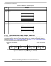
27.3 Functional Description
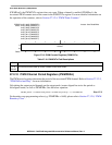
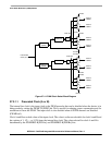
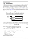
27.3.1 PWM Clock Select
There are four available clocks—clock A, B, SA (scaled A), and SB (scaled B)—all based on the internal
bus clock.
Clock A and B can be programmed to run at 1, 1/2,..., 1/128 times the internal bus clock. Clock SA and
SB use clock A and B respectively as an input and divide it further with a reloadable counter. The rates
available for clock SA and SB are programmable to run at clock A and B divided by 2, 4,..., or 512. Each
PWM channel has the capability of selecting one of two clocks, the prescaled clock (clock A or B) or the
scaled clock (clock SA or SB). The block diagram in Figure 27-14 shows the four different clocks and how
the scaled clocks are created.
1
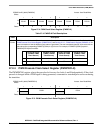
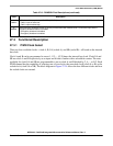
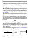
PWM7IL
PWM channel 7 input polarity. If PWMSDN[SDNEN] is set, this bit sets the active level of the PWM 7 channel
0 PWM 7 input is active low
1 PWN 7 input is active high
0
SDNEN
PWM emergency shutdown enable. If set, the pin associated with PWM channel 7 is forced to input and the
emergency shutdown feature is enabled.
0 Emergency shutdown is disabled
1 Emergency shutdown is enabled
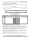
Table 27-13. PWMSDN Field Descriptions (continued)
Field Description