


MCF52211 ColdFire® Integrated Microcontroller Reference Manual, Rev. 2
Freescale Semiconductor 26-1
Chapter 26
Analog-to-Digital Converter (ADC)
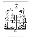
26.1 Introduction
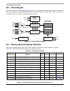
The analog-to-digital converter (ADC) consists of two separate and complete ADCs, each with their own
sample and hold circuits. The converters share a common voltage reference and common digital control
module.
26.2 Features
The ADC’s characteristics include the following:
• 12-bit resolution
• Maximum ADC clock frequency of 5.0 MHz, 200 ns period
• Sampling rate up to 1.66 million samples per second
1
• Single conversion time of 8.5 ADC clock cycles (8.5 × 200 ns = 1.7 μs)
• Additional conversion time of 6 ADC clock cycles (6 × 200 ns = 1.2 μs)
• Eight conversions in 26.5 ADC clocks (26.5 × 200 ns = 5.3 μs) using simultaneous mode
• Ability to simultaneously sample and hold 2 inputs
• Ability to sequentially scan and store up to 8 measurements
• Internal multiplex to select two of 8 inputs
• Power savings modes allow automatic shutdown/startup of all or part of ADC
• Those inputs not selected tolerate injected/sourced current without affecting ADC performance,
supporting operation in noisy industrial environments.
• Optional interrupts at the end of a scan, if an out-of-range limit is exceeded (high or low), or at zero
crossing
• Optional sample correction by subtracting a pre-programmed offset value
• Signed or unsigned result
• Single ended or differential inputs for all input pins with support for an arbitrary mix of input types
1. In loop mode, the time between each conversion is 6 ADC clock cycles (1.2 μs at 5.0 MHz). Using simultaneous conversion,
two samples are captured in 1.2 μs, providing an overall sample rate of 1.66 million samples per second.