


UART Modules
MCF52211 ColdFire® Integrated Microcontroller Reference Manual, Rev. 2
24-20 Freescale Semiconductor
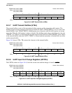
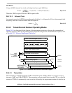
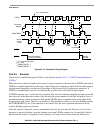
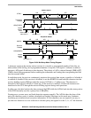
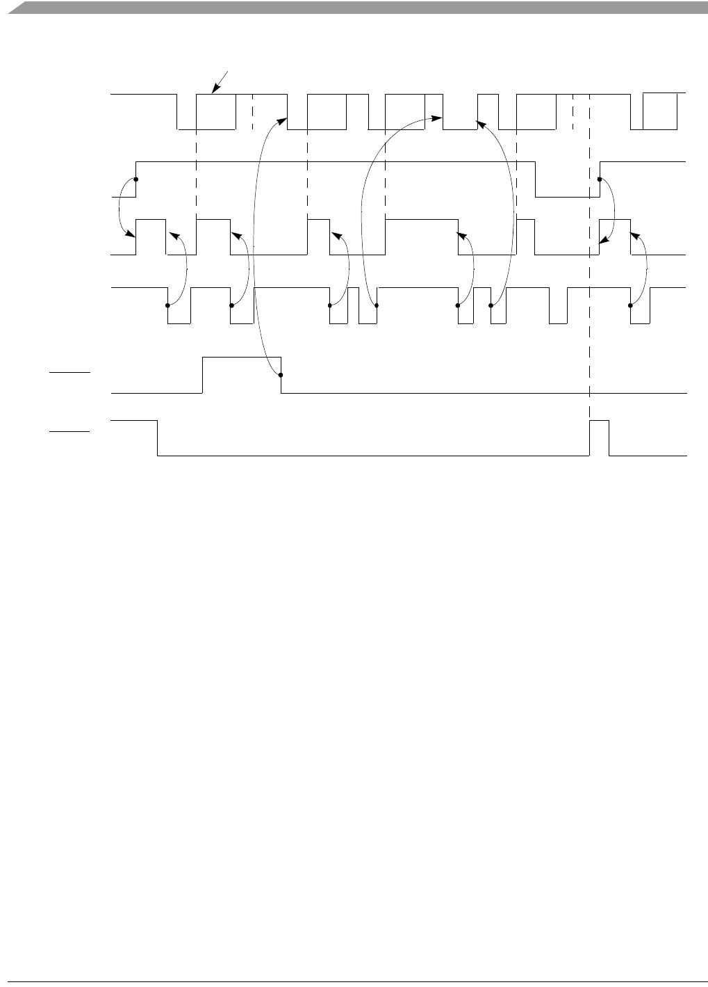
Figure 24-19. Transmitter Timing Diagram
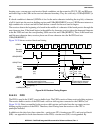
24.4.2.2 Receiver
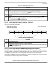
The receiver is enabled through its UCRn, as described in Section 24.3.5, “UART Command Registers
(UCRn).”
When the receiver detects a high-to-low (mark-to-space) transition of the start bit on URXDn, the state of
URXDn is sampled eight times on the edge of the bit time clock starting one-half clock after the transition
(asynchronous operation) or at the next rising edge of the bit time clock (synchronous operation). If
URXDn is sampled high, start bit is invalid and the search for the valid start bit begins again.
If URXDn remains low, a valid start bit is assumed. The receiver continues sampling the input at one-bit
time intervals at the theoretical center of the bit until the proper number of data bits and parity, if any, is
assembled and one stop bit is detected. Data on the URXDn input is sampled on the rising edge of the
programmed clock source. The lsb is received first. The data then transfers to a receiver holding register
and USRn[RXRDY] is set. If the character is less than 8 bits, the most significant unused bits in the
receiver holding register are cleared.
After the stop bit is detected, receiver immediately looks for the next start bit. However, if a non-zero
character is received without a stop bit (framing error) and URXDn remains low for one-half of the bit
period after the stop bit is sampled, receiver operates as if a new start bit were detected. Parity error,
C1
1
C2 C3 Break
C4 C6
Tra nsm it te r
Enabled
USRn[TXRDY]
W
2
WWWWWWW
Manually asserted
by
BIT
-
SET
command
Manually
asserted
Start
break
C5
not
transmitted
C6C4 Stop
break
C3C2C1
1
C1 in transmission
3
UMR2n[TXCTS] = 1
1
Cn = transmit characters
2
W = write
4
UMR2n
[TXRTS] = 1
internal
module
select
UTXDn
UCTSn
3
URTSn
4