


UART Modules
MCF52211 ColdFire® Integrated Microcontroller Reference Manual, Rev. 2
Freescale Semiconductor 24-3
24.2 External Signal Description
Table 24-1 briefly describes the UART module signals.
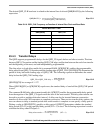
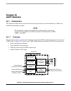
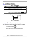
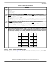
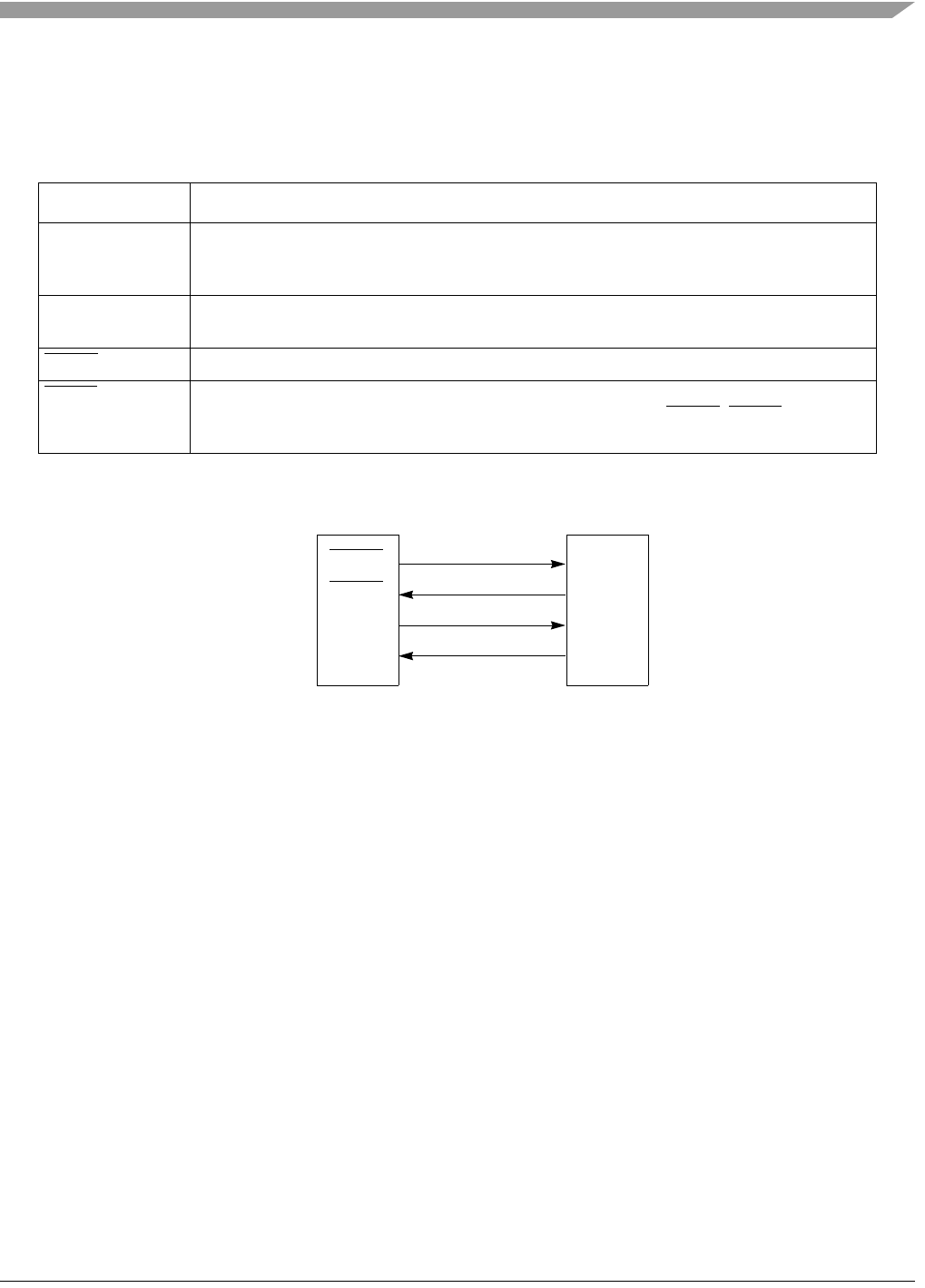
Figure 24-2 shows a signal configuration for a UART/RS-232 interface.
Figure 24-2. UART/RS-232 Interface
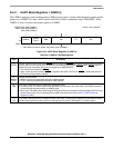
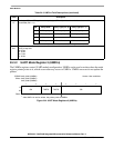
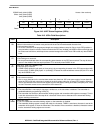
24.3 Memory Map/Register Definition
This section contains a detailed description of each register and its specific function. Flowcharts in
Section 24.5, “Initialization/Application Information,” describe basic UART module programming.
Writing control bytes into the appropriate registers controls the operation of the UART module.
NOTE
UART registers are accessible only as bytes.
NOTE
Interrupt can mean an interrupt request asserted to the CPU or a DMA
request.
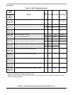
Table 24-1. UART Module Signals
Signal Description
UTXDn Transmitter Serial Data Output. UTXDn is held high (mark condition) when the transmitter is
disabled, idle, or operating in the local loopback mode. Data is shifted out on UTXDn on the
falling edge of the clock source, with the least significant bit (lsb) sent first.
URXDn Receiver Serial Data Input. Data received on URXDn is sampled on the rising edge of the clock
source, with the lsb received first.
UCTS
n Clear-to- Send. This input can generate an interrupt on a change of state.
URTSn Request-to-Send. This output can be programmed to be negated or asserted automatically by
the receiver or the transmitter. When connected to a transmitter’s UCTSn, URTSn can control
serial data flow.
DO2
DI1
DI2
DO1
RS-232 TransceiverUART
URXDn
UTXDn
UCTSn
URTSn