


Queued Serial Peripheral Interface (QSPI)
MCF52211 ColdFire® Integrated Microcontroller Reference Manual, Rev. 2
Freescale Semiconductor 23-9
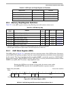
NOTE
The command RAM is accessed only using the most significant byte of
QDR and indirect addressing based on QAR[ADDR].
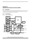
23.4 Functional Description
The QSPI uses a dedicated 80-byte block of static RAM accessible to the module and CPU to perform
queued operations. The RAM is divided into three segments:
• 16 command control bytes (command RAM)
• 32 transmit data bytes (transmit data RAM)
• 32 receive data bytes (receive data RAM)
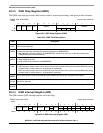
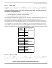
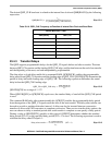
Address: QAR[ADDR] Access: CPU write-only
15 14 13 12 11 10 9 8 7 6 5 4 3 2 1 0
R
WCONTBITSEDTDSCK QSPI_CS 00000000
Reset————————————————
Figure 23-9. Command RAM Registers (QCR0–QCR15)
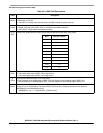
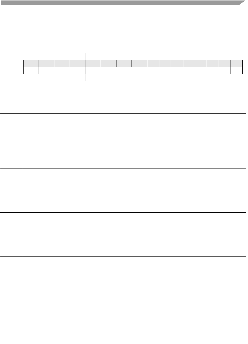
Table 23-9. QCR0–QCR15 Field Descriptions
Field Description
15
CONT
Continuous.
0 Chip selects return to inactive level defined by QWR[CSIV] when a single word transfer is complete.
1 Chip selects return to inactive level defined by QWR[CSIV] only after the transfer of the queue entries (max of 16
words).
Note: To keep the chip selects asserted for transfers beyond 16 words, the QWR[CSIV] bit must be set to control
the level that the chip selects return to after the first transfer.
14
BITSE
Bits per transfer enable.
0 Eight bits
1 Number of bits set in QMR[BITS]
13
DT
Delay after transfer enable.
0 Default reset value.
1 The QSPI provides a variable delay at the end of serial transfer to facilitate interfacing with peripherals that have
a latency requirement. The delay between transfers is determined by QDLYR[DTL].
12
DSCK
Chip select to QSPI_CLK delay enable.
0 Chip select valid to QSPI_CLK transition is one-half QSPI_CLK period.
1 QDLYR[QCD] specifies the delay from QSPI_CS valid to QSPI_CLK.
11–8
QSPI_CS
Peripheral chip selects. Used to select an external device for serial data transfer. More than one chip select may be
active at once, and more than one device can be connected to each chip select. Bits 11-8 map directly to the
corresponding QSPI_CSn pins. If more than four chip selects are needed, then an external demultiplexor can be
used with the QSPI_CSn pins.
Note: Not all chip selects may be available on all device packages. See Chapter 2, “Signal Descriptions,” for details
on which chip selects are pinned-out.
7–0 Reserved, should be cleared.