


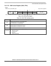
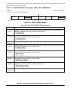
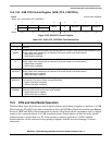

Universal Serial Bus, OTG Capable Controller
MCF52211 ColdFire® Integrated Microcontroller Reference Manual, Rev. 2
Freescale Semiconductor 15-35
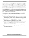
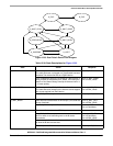
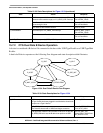
To complete a control transaction to a connected device:
1. Complete all steps discover a connected device
2. Set up the endpoint control register for bidirectional control transfers EP_CTL0[4:0] = 0x0d.
3. Place a copy of the device framework setup command in a memory buffer. See Chapter 9 of the
USB 2.0 specification [2] for information on the device framework command set.
4. Initialize current (even or odd) TX EP0 BDT to transfer the 8 bytes of command data for a device
framework command (i.e. a GET DEVICE DESCRIPTOR).
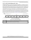
— Set the BDT command word to 0x00080080 – Byte count to 8, own bit to 1
— Set the BDT buffer address field to the start address of the 8 byte command buffer
5. Set the USB device address of the target device in the address register (ADDR[6:0]). After the USB
bus reset, the device USB address is zero. It is set to some other value (usually 1) by the Set
Address device framework command.
6. Write the token register with a SETUP to Endpoint 0 the target device default control pipe
(TOKEN=0xD0). This initiates a setup token on the bus followed by a data packet. The device
handshake is returned in the BDT PID field after the packets complete. When the BDT is written
a token done (INT_STAT[TOK_DNE]) interrupt is asserted. This completes the setup phase of the
setup transaction as referenced in chapter 9 of the USB specification.
7. To initiate the data phase of the setup transaction (i.e., get the data for the GET DEVICE descriptor
command) set up a buffer in memory for the data to be transferred.
8. Initialize the current (even or odd) TX EP0 BDT to transfer the data.
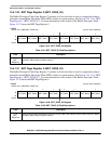
— Set the BDT command word to 0x004000C0 – Byte count to the length of the data buffer in
this case 64, own bit to 1, Data toggle to Data1.
— Set the BDT buffer address field to the start address of the data buffer
9. Write the token register with a IN or OUT token to Endpoint 0 the target device default control
pipe, an IN token for a GET DEVICE DESCRIPTOR command (TOKEN=0x90). This initiates an
IN token on the bus followed by a data packet from the device to the host. When the data packet
completes the BDT is written and a token done (INT_STAT[TOK_DNE]) interrupt is asserted. For
control transfers with a single packet data phase this completes the data phase of the setup
transaction as referenced in chapter 9 of the USB specification.
10. To initiate the Status phase of the setup transaction set up a buffer in memory to receive or send the
zero length status phase data packet.
11. Initialize the current (even or odd) TX EP0 BDT to transfer the status data.
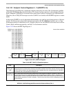
— Set the BDT command word to 0x00000080 – Byte count to the length of the data buffer in
this case 0, own bit to 1, Data toggle to Data0.
— Set the BDT buffer address field to the start address of the data buffer
12. Write the token register with a IN or OUT token to Endpoint 0 the target device default control
pipe, an OUT token for a GET DEVICE DESCRIPTOR command (TOKEN=0x10). This initiates
an OUT token on the bus followed by a zero length data packet from the host to the device. When
the data packet completes the BDT is written with the handshake form the device and a token done
(INT_STAT[TOK_DNE]) interrupt is asserted. This completes the data phase of the setup
transaction as referenced in chapter 9 of the USB specification.