


Backup Watchdog Timer (BWT) Module
MCF52211 ColdFire® Integrated Microcontroller Reference Manual, Rev. 2
7-4 Freescale Semiconductor
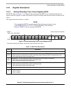
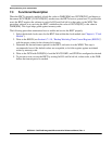
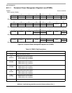
7.2.2.2 Backup Watchdog Timer Modulus Register (WMR)
The WMR, shown in Figure 7-3, contains the value (modulus) that is loaded into the BWT count register
(WCNTR) when the BWT is serviced. This value effectively corresponds to the BWT’s timeout period.
The software must service the timer within this period to avoid a reset. The timeout period is a function of
the WMR, the period of the BWT’s input clock, and the device operating mode, as shown in the equation
in Table 7-3.
The WMR is a read-always/write-once register; after the register is written, the contents cannot be changed
until the next Power-On Reset event occurs.
NOTE
To ensure that the BWT is properly enabled, the software must write a value
to the WMR prior to writing to the WCR.
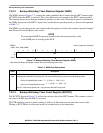
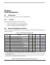
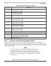
7.2.2.3 Backup Watchdog Timer Count Register (WCNTR)
The WCNTR, shown in Figure 7-4, reflects the current value in the BWT counter. This counter is reset to
the value in WMR when the BWT is serviced.
WCNTR should be read as a whole; reading it with two 8-bit reads may not return the correct value.
Writing to WCNTR has no effect and results in a normal write cycle termination.
IPSBAR
Offset: 0x14_0002 (WMR)
Access: Supervisor read/write
1514131211109876543210
R
WM
W
Reset
1
1
After Power-On Reset; the register contents are preserved during warm resets.
1111111111111111
Figure 7-3. Backup Watchdog Timer Modulus Register (WMR)
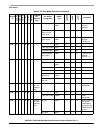
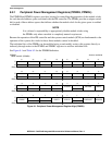
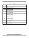
Table 7-3. WMR Field Descriptions
Field Description
15–0
WM
BWT modulus. This value is loaded into the BWT count register (WCNTR) when the BWT is serviced. It thus
corresponds to the BWT’s timeout period. The actual timeout period is given by the following equations:
Device in Stop/Wait/Doze mode:
Device not in Stop/Wait/Doze mode:
where T is the timeout period and τ is the period of the BWT’s input clock.
TWM1+()4096 16+⋅[]τ=
TWM1+()4096 4+⋅[]τ=